


38
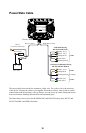
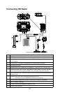
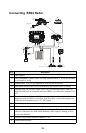
Connecting BR24 Radar
Key Description
A HDS Display.
B BR24 BroadBand™ Radar system for HDS. Includes parts B, C and D (not included
in US) and E (2 m 6ft)
C Scanner cable. 10 m (33 ft) : Optional 20 m (65 ft) and 30 m (98 ft).
D RI10 Radar interface box (Used with MARPA) (Not included with US version)
E Ethernet cable. BR24 comes with a 2 m (6.5 ft) 5 pin cable and a RJ45 cable (US
only) The BR24 can be connected directly to HDS or via a Network Expansion Port
(G)
F Power control bus: In this case BR24 is connected to Power Control Bus. BR24 is
turned on when the HDS is powered on. Note the yellow wire must be connected to
either the power control bus or to 12 V DC supply)
G RC42 Compass
H LSS1 - StructureScan black box
I SimNet drop cable: (0.3 m 1ft, 2 m 6ft or 5 m 15ft ) The RI10 interface box and
HDS are connected to the NMEA2000 backbone. BR24 requires heading at 10 hz
to calculate MARPA
J SimNet to NMEA2000 adapter kit (000-0127-45)
K NMEA2000 Backbone
+
_
D
F
F
J J
G
I I
H
A
E
B
C
D
Power
Scanner cable
SimNet
Network