


9
5. EXTERNAL WIRING
5.1 CC-Link Dedicated Cable Wiring
This section explains how to connect the safety master module, safety
remote I/O module, standard remote I/O module and/or remote device
module with CC-Link dedicated cables.
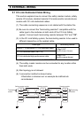
(1) The cable connecting sequence is not related with the station No.
(2) Be sure to connect the "terminating resistors" compatible with the
cable type to the modules on both ends of the CC-Link Safety
system. Connect each terminating resistor between "DA" and "DB".
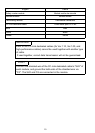
(3) In the CC-Link Safety system, the terminating resistor to be used is
different depending on the applied cable.
* This resisters are provided with QS0J61BT12
(4) The safety master module can be connected to any location other
than both ends.
(5) Star topology is not allowed.
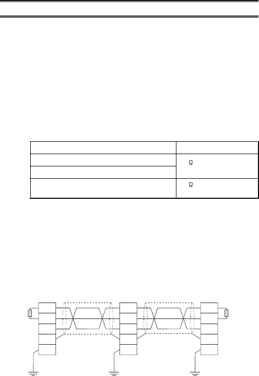
(6) A connection method is shown below.
L'illustration ci-dessous est un exemple de méthode de
raccordement.
Cable type Terminating resister
Version 1.10 compatible CC-Link dedicated cable
110 1/2 W *
(brown-brown-brown)
CC-Link dedicated cable (Ver.1.00)
CC-Link dedicated high-performance cable
130 1/2 W
(brown-orange-brown)
Terminating
resistor
Terminating
resistor
Safety master module Remote module Remote module
DA
DB
DG
SLD
FG
DA
DB
DG
FG
SLD
DA
DB
DG
FG
SLD
CC-Link dedicated cable CC-Link dedicated cable
(Blue)
(White)
(Yellow)