15
Wiring
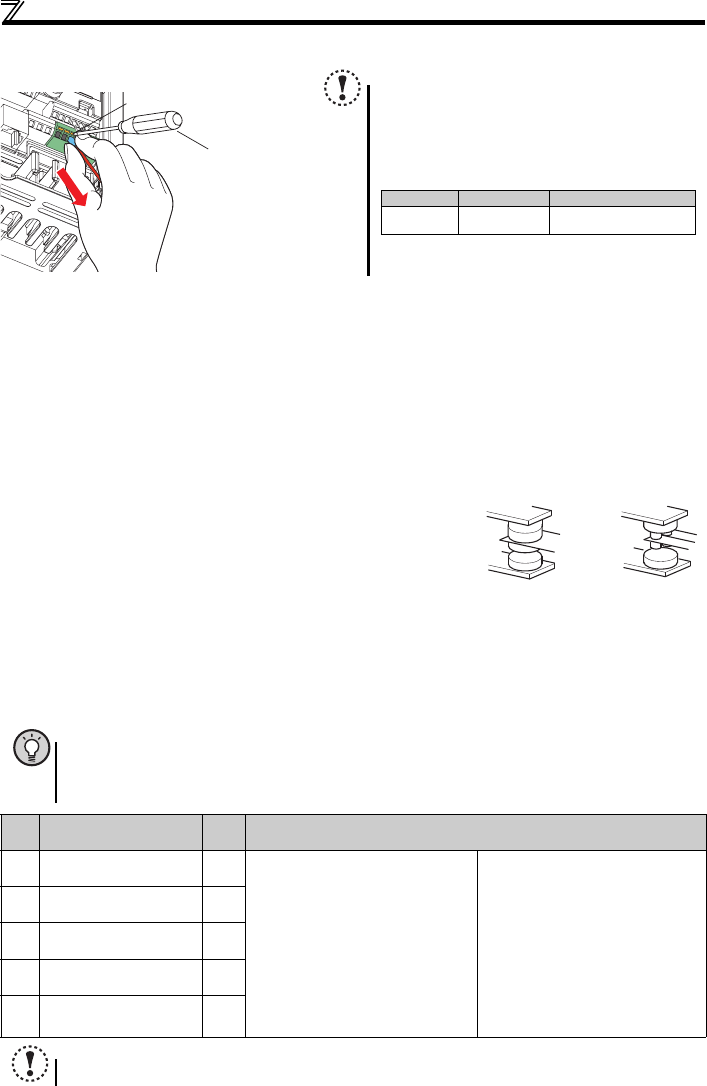
zWire removal
(3) Control circuit common terminals (SD, 5, SE)
Terminals SD, SE and 5 are common terminals for I/O signals.(All common terminals are isolated from each other.) Do not
earth them. Avoid connecting the terminals SD and 5 and the terminals SE and 5.
Terminal SD is a common terminal for the contact input terminals (STF, STR, RH, RM, RL) and frequency output signal (FM).
The open collector circuit is isolated from the internal control circuit by photocoupler.
Terminal 5 is a common terminal for the frequency setting signals (terminals 2 or 4). It should be protected from external noise
using a shielded or twisted cable.
Terminal SE is a common terminal for the open collector output terminal (RUN). The contact input circuit is isolated from the
internal control circuit by photocoupler.
(4) Wiring instructions
1)It is recommended to use the cables of 0.3mm
2
to 0.75mm
2
gauge for connection to the control circuit terminals.
2)The maximum wiring length should be 30m (200m for terminal FM).
3)Do not short across terminals PC and SD. Inverter may be damaged.
4)When using contact inputs, use two or more parallel micro-signal contacts or
twin contacts to prevent contact faults since the control circuit input signals are
micro-currents.
5)Use shielded or twisted cables for connection to the control circuit terminals
and run them away from the main and power circuits (including the 200V relay
sequence circuit).
6)Do not apply a voltage to the contact input terminals (e.g. STF) of the control circuit.
7)Always apply a voltage to the fault output terminals (A, B, C) via a relay coil, lamp, etc.
2.3.5 Assigning signals (output stop signal (MRS), reset signal (RES), etc.) to contact
input terminals
Pull the wire with pushing the open/close button all the
way down firmly with a flathead screwdriver.
POINT
y Use Pr.178 to Pr.182 (input terminal function selection) to select and change the functions assigned to input
terminals.
To assign the output stop signal (MRS) to the terminal RH, for example, assign "24" to Pr.182 RH terminal
function selection. (Refer to page 4 to change a parameter setting value.)
Pr. Name
Initial
Value
Range
178
STF terminal function selection
60
0: Low-speed operation command (RL)
1: Middle-speed operation command (RM)
2: High-speed operation command (RH)
3: Second function selection (RT)
4: Terminal 4 input selection (AU)
5: JOG operation selection (JOG)
7: External thermal relay input (OH)
8: Fifteen speed selection (REX)
10:Inverter operation enable signal (X10)
(FR-HC/FR-CV connection)
12: PU operation external interlock (X12)
14: PID control valid terminal (X14)
16: PU-External operation switchover (X16)
18: V/F switchover (X18)
24: Output stop (MRS)
25: Start self-holding selection (STOP)
60: Forward rotation (STF)
∗1
61: Reverse rotation (STR) ∗2
62: Inverter reset (RES)
65: PU-NET operation switchover (X65)
66:External-NET operation switchover
(X66)
67: Command source switchover (X67)
9999: No function
∗1 Assigned to STF terminal (Pr. 178) only
∗2 Assigned to STR terminal (Pr. 179) only
179
STR terminal function selection
61
180
RL terminal function selection
0
181
RM terminal function selection
1
182
RH terminal function selection
2
NOTE
y Changing the terminal assignment using Pr.178 to Pr.182 (input terminal function selection) may affect the other functions.
Set parameters after confirming the function of each terminal.
Open/close button
Flathead screwdrive
r
NOTE
y Pulling out the terminal block forcefully without pushing
the open/close button all the way down may damage the
terminal block.
y Use a small flathead screwdriver (Tip thickness: 0.4mm/
tip width: 2.5mm).
If a flathead screwdriver with a narrow tip is used,
terminal block may be damaged.
Products available on the market :(as of Oct. 2008)
y Place the flathead screwdriver vertical to the open/close
button. In case the blade tip slips, it may cause damage
to inverter or injury.
Product Type Manufacturer
Flathead
screwdriver
SZF 0- 0,4 x 2,5 Phoenix Contact Co.,Ltd.
Micro signal contacts Twin contacts


