


PAGE 32 — BA-SERIES WALK-BEHIND TROWEL— OPERATION & PARTS MANUAL — REV. #2 (03/19/04)
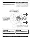
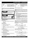
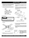
Trowel Arm Flatness Test
1. Using a piece of 19 mm (3/4 in.) thick steel plate or any surface
which is
true
and
flat
, check all
six sides
of each trowel arm
for flatness.
2. Check each of the six sides of the trowel arm (hex section
only) using a ten thousands of an inch (max.) feeler gauge
(Figure 46) between the flat of the trowel arm and an
ex
-
tremely flat
test surface.
3. If the trowel arm is found to be
uneven
or
bent
, replace the
trowel arm. A bent trowel will not allow the trowel to operate
in a smooth fluid rotation.
4. Next, check each of the six sides of the round machined shaft
section of the trowel arm. Each section should have the
same
clearance
between the round of the trowel arm shaft and the
test surface.
Figure 46. Trowel Arm Flatness Test
BA-SERIES TROWEL — MAINTENANCE
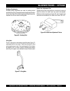
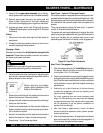
3. Should the trowel arm inserts (bronze bushing ) come out
with the trowel arm, remove the bushing from the trowel arm
and set aside in a safe place. If the bushing is retained inside
the spider plate, carefully remove the bushing.
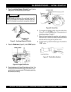
4. Examine the bronze trowel arm bushing insert (Figure 44),
clean if necessary. Replace bushing if out of round or worn.
Figure 44. Bronze Bushings
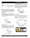
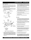
Trowel Blade Removal
Figure 45. Trowel Blades
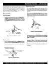
2.
Wire brush
any build-up of concrete from all six sides of the
trowel arm. Repeat this for the remaining three arms.
NOTE
Trowel arms can be damaged by
rough handling or by striking
exposed plumbing or forms while in
operation.
ALWAYS
look-out for
objects which might cause damage
to the trowel arms.
1. Remove the trowel blades from the trowel arm by removing
the three hex head bolts (Figure 45) from the trowel arm. Set
blades aside.
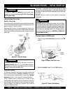
ALWAYS disconnect spark plug and secure away from the
engine before performing service or maintenance.
WARNINGWARNING
WARNINGWARNING
WARNING