


CV SERIES VIBRATOR MOTOR • OPERATION AND PARTS MANUAL — REV. #0 (04/30/13) — PAGE 15
GENERAL INFORMATION
Multiquip's CV Series Vibrator Motors are designed to
work with flex shafts and vibrator heads for consolidation
of fresh concrete to ensure optimum strength and durability.
See Table 2 for the required shafts for the different vibrator
motor models.
These vibrator motors have large vibration-isolated handles
to protect the motor and the operator. They have a quick-
disconnect knob for easy shaft removal.
The cassette-style motor improves durability and
performance by minimizing friction and enabling the motor
to maintain optimum RPM.
The flow-through ventilation feature of these motors
reduces contamination by taking in air from the rear of
the motor.
FLEXIBLE SHAFTS
Multiquip's flex-shafts vibrator heads are designed to work
in medium to high slump concrete. Typical applications
include small pours, slabs, driveways, stem walls and
footings.
Typical shaft lengths range from 2 to 21 feet (0.6 to
6.4 meters). See Table 6 for recommended shaft lengths.
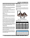
Steel heads, attached to one end of the flex-shaft, generate
vibration via an eccentric rotator that consolidates the
concrete by removing air pockets. The round head design
allows for the transmission of vibration in all directions.
There are 7 different steel head sizes that range from
7
/
8
to 2
5
/
8
inches in diameter. Typical vibration frequency for
these vibrating heads range from 9,200 to 12,150 VPM
with 1-inch slump when using electric motors.
CONSOLIDATION
Consolidation eliminates pockets of air bubbles maximizing
strength and eliminating voids. Vibrators consolidate
concrete by transmitting shock waves which allow the
aggregate to float freely while pushing lighter trapped air
up and out of the concrete mix.
A properly consolidated concrete pour will display a thin line
of mortar appearing along the form near the vibrator and the
coarse aggregate has been dispersed evenly throughout
the pour and is not visible.
VIBRATION TIME
Vibration time depends on frequency. The higher the
frequency, the less vibration time is required for the job.
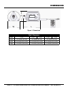
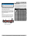
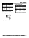
VIBRATION RANGE
Vibration range (Figure 2) can be defined as "Area of
Influence". This area of influence (vibrating radius) is the
distance from the center of the vibrator to the outer most
edge.
Figure 2. Vibrator Radius/Spacing
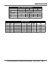
Table 4 shows the vibration radius and spacing for a given
vibrator head diameter.
R
AREA
OF INFLUENCE
(VIBRATING RADIUS)
VIBRATOR HEAD
INSERTION SPACING
D
Table 4. Vibrating Radius/Insertion Spacing
Vibrating
HD. Model
Vibrator HD.
Dia. in. (mm)#
Vibration
Radius (R)
Vibrator
Spacing (D)
900HD
7
/
8
(22) 4 (102) 6 (152)
1000HD 1
1
/
16
(27) 5.5 (140) 8.25 (210)
1400HD 1
3
/
8
(35) 8 (203) 12 (305)
1700HD 1
11
/
16
(43) 12 (305) 18 (457)
2100HD 2
1
/
8
(54) 14 (356) 21 (533)
2600HD 2
5
/
8
(67) 18 (457) 27 (686)
NOTICE
Radius (area of influence R) and vibrator head spacing
(D) are expressed in inches/millimeters. Radius and
distance values expressed in Table 4 are only to be
used as a general guide. Values are subject to change.