


PAGE 16 — CV SERIES VIBRATOR MOTOR • OPERATION AND PARTS MANUAL — REV. #0 (04/30/13)
GENERAL INFORMATION
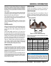
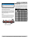
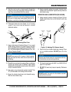
When determining which head to choose it is important
to access the application; mainly the dimensions of the
application. Select the vibrator head based on its radiating
radius characteristics. Refer to Table 4.
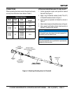
Select the vibrating head that covers the largest possible
area without excessive overkill. This will allow for more
efficient productivity. General rule of thumb is: DO NOT
select a vibrator head which has a vibration radius of more
than twice the width of the form.
Example:
If the form width is 9 inches (229 mm) the selected vibrator
head radius should not exceed an 18 inch (457 mm) radius.
In this example the 2600HD vibrator head would be the
recommended choice. Refer to Table 4 and Figure 3.
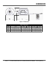
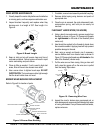
Figure 3. Head Selection
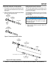
NOTICE
Vibrator head spacing distance (D) is calculated by
multiplying the vibrating head radius (area of influence)
by 1.5.
AREAOFINFLUENCE
(VIBRATINGRADIUS)
VIBRATORHEAD
INSERTIONSPACING
VIBRATORHEAD
INSERTIONPOINT
CONCRETE
TOOSMALLAREA
OFINFLUENCE
(VIBRATINGRADIUS)
NOVIBRATION
NOVIBRATION
CORRECT
FORM
WIDTH
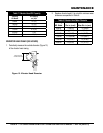
EXTENSION CORDS
When extension cords are used, refer toTable 5 for the
correct size and lengths needed. Using an extension
cord with a wire gauge smaller than or longer than
the recommended size could result in reduced motor
performance and/or damage to the motor or extension
cord due to overheating.
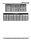
Table 5. Extension Cord Sizes (AWG)
Ampere
Rating
Range
Volts Length of Cord in Feet
115V 25 ft. 50 ft. 100 ft. 150 ft. 200 ft. 250 ft.
230V 50 ft. 100 ft. 200 ft. 300 ft. 400 ft. 500 ft.
0 - 2 18 18 18 16 16 14
2 - 3 18 18 16 14 14 12
3 - 4 18 18 16 14 12 12
4 - 5 18 18 14 12 12 10
5 - 6 18 16 14 12 10 10
6 - 8 18 16 12 10 10 8
8 - 10 18 14 12 10 8 8
10 - 12 16 14 10 8 8 6
12 - 14 16 12 10 8 6 6
14 - 16 16 12 10 8 6 6
16 - 18 14 12 8 8 6 4
18 - 20 14 12 8 6 6 4