


CV SERIES VIBRATOR MOTOR • OPERATION AND PARTS MANUAL — REV. #0 (04/30/13) — PAGE 17
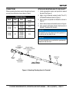
SETUP
CONNECTIONS
When connecting the vibrator motor to flex shaft and heads,
use only the combination shown below in Table 6.
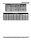
Table 6. Shaft Sizes
Model Shaft Head
Max. Shaft
Length
CV1A FSN
900HD
1000HD
21 ft.
CV2A
CV2B
FS
1400HD
1700HD
20 ft.
2100HD 21 ft.
CV3A
CV3B
FS
1400HD
1700HD
2100HD
2600HD
35 ft.
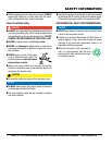
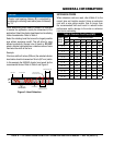
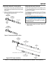
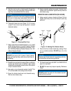
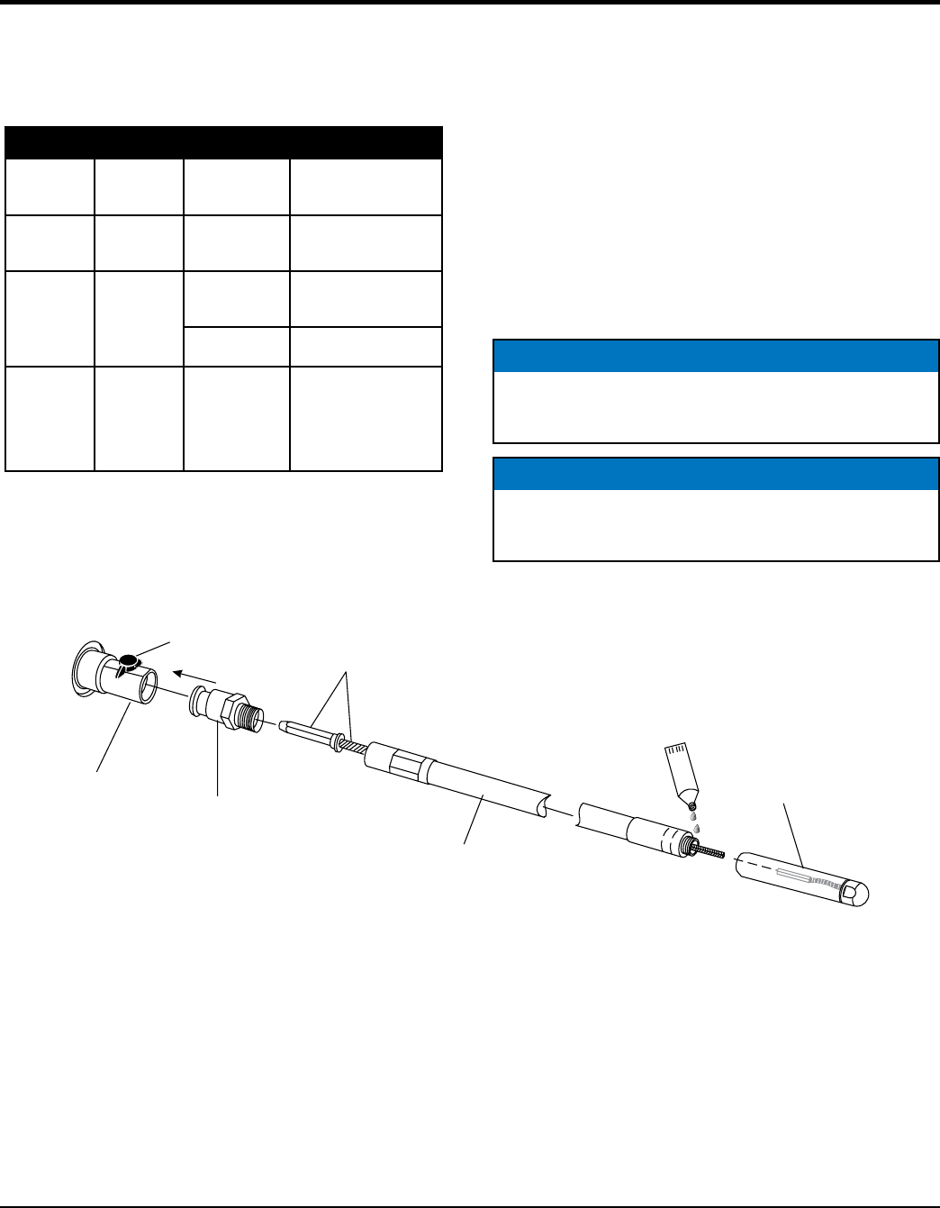
ATTACHING VIBRATING HEAD TO FLEX-SHAFT
1. Locate appropriate coupler and spindle for desired
flex-shaft. See Figure 4.
2. Apply a ring of anaerobic sealant (Loctite™ No. 271)
to flexshaft threads as shown in Figure 4.
3. Insert coupler and spindle into flexshaft as shown in
Figure 4.
4. Attach vibrator head onto flexshaft as shown in Figure 4.
5. Use a wrench and tighten vibrator head securely to
flexshaft. Threads are left-handed.
NOTICE
All flexshaft cores have been lubricated (greased) at
the factory and are ready for use.
NOTICE
FS series flexshafts use a spindle that is permanently
attached to the wire core.
Figure 4. Attaching Vibrating Head to Flexshaft
QUICK
DISCONNECT
KNOB
VIBRATOR
HEAD
QUICK
DISCONNECT
COUPLER
FSN/FS SERIES
FLEXIBLE SHAFT
SPINDLE AND
CORE ARE ATTACHED
(1 PIECE)
MOTOR
END
LOCTITE™271
PIPE THREAD