


LT12 SERIES LIGHT TOWER • OPERATION MANUAL — REV. #12 (01/20/09) — PAGE 29
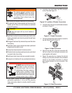
Lowering the Mast
Turn the mast extension winch counterclockwise, and 1.
observe that the mast begins to lower.
Continue turning the winch counterclockwise until the 2.
mast has been fully retracted (slack in the cable).
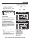
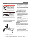
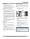
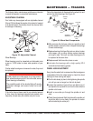
Stowing the Mast to Horizontal Position
Refer to Figure 17 for the location of components:
Remove the mast lock/release pin to allow the mast 1.
section to be lowered to the horizontal position. Pull
out the mast lock handle to unlatch.
Turn the vertical mast winch counterclockwise and 2.
observe that mast begins to approach the horizontal
position. The mast lock handle can now be released.
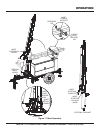
Continue turning the vertical mast winch in the 3.
counterclockwise direction. As the mast approaches
the mast cradle support, pull the retaining pin and
then the cradle lock/release pin to allow the mast to
rest in the cradle.
Once the mast is resting in the mast cradle support, 4.
insert the cradle lock/release pin and secure with
retaining pin to keep mast in place.
Rotating the Mast
To change the direction that the lamps are facing, the mast
can be rotated.
Refer to Figure 17 for the location of components.
With the mast in the deployed position (vertical), 1.
unscrew the mast rotation locking knob to release the
mast for rotation.
Grip the mast rotation handles and rotate the mast until 2.
the lamps are facing the desired direction.
When the lamps are facing the desired direction, 3.
tighten the mast rotation lock knob to lock the mast
in place.
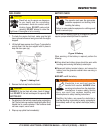
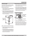
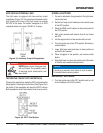
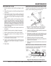
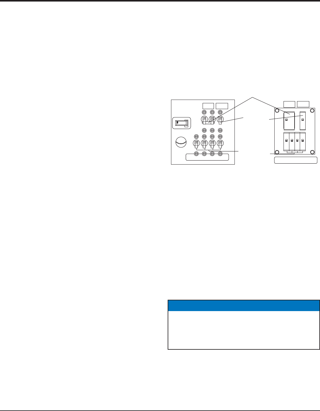
TURNING ON THE LAMPS
The main circuit breaker (25 amps) and 4 lamp circuit
breakers (10 amps each) are located on the upper
control panel (Figure 18). Each lamp has a 10-amp circuit
breaker.
Place the main circuit breaker (Figure 18) on the control 1.
panel to the ON position.
Control Panel Circuit BreakersFigure 18.
Set lamp circuit breaker #1 on the control panel to the 2.
ON position.
Wait a few minutes for the ballast to activate. Observe 3.
that lamp #1 is ON.
Repeat steps 2 and 3 for lamps 2 through 4.4.
If all the lamp circuit breakers are in the ON position 5.
(up), then all of the lights should be on.
If any of the lamps are not on, refer to the troubleshooting 6.
section of this manual.
Close all cabinet doors.7.
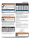
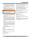
LIGHT CONTROL/BREAKER
HOURS
HOURS
1/10
0.0
SenDEC
HOURS
1/10
120 VAC/15A
GFCI
BREAKER
240 VAC/30A
MAIN
BREAKER
GFCI
RECEPTACLE
CIRCUIT
BREAKER
LAMP
CIRCUIT
BREAKERS
OLD STYLE
NEW STYLE
MAIN
CIRCUIT
BREAKER
LIGHT CONTROL/BREAKER
120 VAC/15A
GFCI
BREAKER
240 VAC/30A
MAIN
BREAKER
NOTICE
NEVER operate the light tower with the engine
compartment doors open. Operation with the doors
open may cause insuffi cient cooling to the unit, and
damage may result.
OPERATION