


PAGE 30 — LT12 SERIES LIGHT TOWER • OPERATION MANUAL — REV. #12 (01/20/09)
APPLYING AN EXTERNAL LOAD
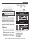
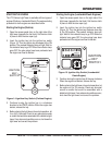
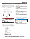
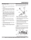
The light tower is equipped with two auxiliary output
receptacles (Figure 19). The uppermost receptacle (twist-
lock) located at the front of the light tower can provide
240 VAC at 25 amps. The bottom receptacle is a GFCI
receptacle which can supply 120 VAC at 15 amps.
Auxiliary Output ReceptaclesFigure 19.
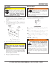
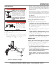
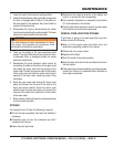
TESTING THE 120 VAC GFCI RECEPTACLE
Pressing the reset button resets the GFCI receptacle after
being tripped. Pressing the test button (See Figure 20) in
the center of the receptacle will check the GFCI function.
Both receptacles should be tested at least once a month.
GFCI Test ButtonFigure 20.
DANGER
NEVER grab or touch a live power cord
with wet hands. The possibility exists
of electrical shock, electrocution, and
even death!
OPERATION
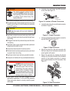
NORMAL SHUTDOWN
If a load is attached to the generator of the light tower, 1.
remove the load.
Set the four lamp circuit breakers on the control panel 2.
to the OFF position.
Place the MAIN circuit breaker on the control panel to 3.
the OFF position.
Wait a few seconds and observe that all four lamps 4.
are OFF.
Let the engine idle for a few minutes with no load.5.
Turn the ignition key to the OFF position. Store key in 6.
a safe location.
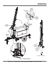
Lower light tower mast and place in stow position as 7.
outlined in this manual.
Place outriggers in tow position, and remove chock 8.
blocks.
Store light tower in a clean, dry location out of the reach 9.
of children and unauthorized personnel.
EMERGENCY SHUTDOWN
Turn the ignition key to the OFF position and turn all 1.
circuit breakers to the OFF position.
NOTICE
If servicing is required, allow lamps to cool for about
15 minutes before removing lamps.