


PAGE 16 — HTH-8 FT. RIDE-ON POWER TROWEL — OPERATION AND PARTS MANUAL — REV. #6 (02/22/11)
HTH — CONTROLS AND INDICATORS
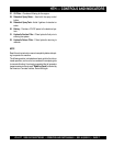
13. Radiator/Filler Cap –Holds coolant or water necessary
to keep engine at a safe operating temperature. Remove
this cap to add water or antifreeze.
14. Kill Switch - Shuts down engine when operator is not
sitting in seat.
15. Lights – Low voltage halogen light.
16. Hydraulic Oil Filler Cap – Remove this cap to add hy-
draulic oil.
17. Hydraulic Oil Sight Glass - Indicates the level of the
hydraulic oil in the reservoir.
18. Right Foot Pedal – Controls blade speed. Slow blade
speed is accomplished by slightly depressing the foot
pedal. Maximum blade speed is accomplished by fully
depressing the foot pedal.
19. Spray Nozzle – Spray nozzle for retardant.
20. Left Foot Riser – Operator foot rest pedal.
21. Fuel Gauge/Filler Cap - Indicates the amount of fuel in
the fuel tank. Remove this cap to add fuel.
22. Hydraulic Reservoir – Part of frame. Holds hydraulic oil
necessary for pump operation.
23. Lift Loops –Located on both the left and right sides of
the main frame. Used when the trowel must be lifted onto
a concrete slab.
24. Engine Oil Dipstick – Indicates engine oil level.
25. Engine Oil Filler Cap - Remove this cap to add engine
oil.
26. Air Filter – Prevents dirt and other debris from entering
the fuel system.
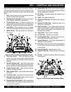
Figure 2. HTH Controls and Indicators (Front)
Figure 3. HTH Controls and Indicators (Rear)
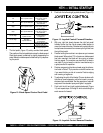
Figures 2 and 3 show the location of the controls, indicators
and general maintenance parts. Each control may perform more
than one function. All functions of each control are described
below.
1. Seat – Place for operator to sit. Engine will not start unless
operator is seated. Seat is adjustable.
2. Steering Control (right side) -Allows the unit to move in
either a forward, reverse left or right direction.
3. Throttle Control Lever – Controls the speed of the
engine. Move the hand lever forward to increase engine
speed (high), backwards to decrease engine speed (low).
4. Light Switch – When activated, turns on six halogen
lights. Lights offer better visibility when working indoors.
5. Ignition Switch – With key inserted turn clockwise to
start engine.
6. Twin Pitch Control – Both pitch towers are linked
together. One crank may be turned to adjust the blade
pitch simultaneously or individually control for each set
of blades.
7. Pre-Heat Indicator Light - Lights blue during engine
start-up. Indicates that engine glow plugs are being pre-
heated. Light will go off after approximately 10 seconds.
8. Charge Indicator Light - Lights red when electrical
system is not charging properly.
9. Water Indicator Light - Lights red when water tempera-
ture is high.
10. Oil Indicator Light - Lights red when oil pressure is low.
11. Steering Control (left side) -Allows the unit to move in
a forward or reverse direction only.
12. Retardant Spray Control Button – When pressed allows
retardant spray to flow through the spray nozzle located
at the front of the machine.