


HTH-8 FT. RIDE-ON POWER TROWEL — OPERATION AND PARTS MANUAL — REV. #6 (02/22/11) — PAGE 23
HTH — MAINTENANCE
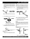
Changing A Blade
Whiteman recommends that all the blades on the entire ma-
chine be changed at the same time. If only one or some of the
blades are changed at one time, the machine will not finish
concrete consistently and the machine may wobble or bounce.
1. Place the machine on a flat, level surface. Adjust the blade
pitch control to make the blades as flat as possible. Note
the blade orientation on the trowel arm. This is important
for ride-on trowels as the two sets of blades counter-rotate.
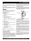
Lift the machine up, placing blocks under the main guard
ring to support it.
2. Remove the bolts and lock washers on the trowel arm,
and then remove the blade.
3. Scrape all concrete and debris from the trowel arm. This
is important to properly seat the new blade.
4. Install the new blade, maintaining the proper orientation
for direction of rotation.
5. Affix the bolts and lock washers.
6. Repeat steps 2-5 for all remaining blades.
Checking Hydraulic Pressure
It should be mentioned that most hydraulic problems are a
result of low fluid levels. Before checking any other possibilities,
make sure the hydraulic fluid level is half way up the sight glass
which is located at the right end of the frame.
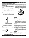
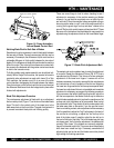
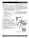
Hydraulic pressure can be checked using a pressure gauge
(Figure 18) with a range of at least 5,000 psi. The pressure taps
are located on the front side of the hydraulic pumps on elbows.
The 1/8" pipe plugs can be removed and a hose, attached to
the gauge, screwed into each port. It is best to use two gauges
simultaneously, but it is possible to use only one gauge and
repeat the procedure for each side.
To fully test the hydraulic system, the spiders will need to be
locked so that they cannot rotate. This can easily be done by
wrapping a chain around an arm on each spider, thus chaining
them together in the back of the trowel.
Figure 18. Pressure Gauge (Hydraulic Pump)
Once the pressure gauges are installed and the spiders chained
together, the system can be checked.
With the foot pedal in the idle position and the engine at full
speed, the pressure should be 200 to 300 psi. If the pressure is
less than 200 psi, the charge system may need to be inspected
and/ or serviced. In particular, the suction filter and charge
pump relief valve should be checked. The suction filter may
be plugged, or the relief valve may be stuck. Either condition
may cause low charge pressure.
With the engine at 50% to 70% of full speed, and spiders
chained together, slowly depress the foot pedal and read the
gauges. The pressure should get to at least 3,100 psi. If the
pressure will not attain 3,100 psi, the pump should be inspected
and/or serviced by an authorized service representative.