


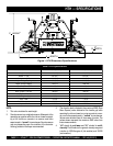


HTH-8 FT. RIDE-ON POWER TROWEL — OPERATION AND PARTS MANUAL — REV. #6 (02/22/11) — PAGE 21
HTH — MAINTENANCE
NOTE
See the engine manual supplied with your machine for ap-
propriate engine maintenance schedule and troubleshooting
guide for problems.
At the front of the book (Page B) there is a “Daily Pre-Operation
Checklist”. Make copies of this checklist and use it on a daily
basis.
CAUTION!
Disconnect spark plug wires and battery cables before attempt-
ing any service or maintenance on the ride-on trowel.
MAINTENANCE SCHEDULE
Daily (8-10 Hours)
1. Check the fluid levels in the engine and reservoir, fill as
necessary.
Weekly (30-40 Hours)
1. Relube arms, thrust collar and clutch
2. Replace blades if necessary.
3. Check and clean or replace the engine air filter as neces-
sary.
4. Replace engine oil and filter as necessary, see engine
manual.
Monthly (100-125 Hours)
1. Remove, clean, reinstall and relube the arms and thrust
collar. Adjust the blade arms.
Yearly (500-600 Hours)
1. Check and replace if necessary the arm bushings, and
thrust collar bushings.
2. Check pitch control cables for wear.
3. Adjust blade speed.
4. Replace hydraulic fluid and both hydraulic filters.
NOTE
After the first 200 hours, replace the hydraulic filter cartridges.
MAINTENANCE PROCEDURES
Checking/Adjusting Blade Speed
Because the two hydraulic drive motors operate independent
of each other, the blade speed between them may vary. If the
unit’s steering is difficult to control, the blade speeds may need
to be checked, or if the spider is spinning noticeably faster
or slower than the other side, the blade speed may need to
be checked. It is also recommended that the blade speed be
checked at least once a year.
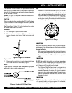
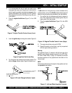
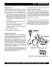
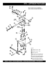
Figure 15. Blade Speed Control Foot Pedal
ROD END
ADJUSTMENT
NUT
Blade speed adjustment is a two-step process. First, the left
spider’s speed should be checked and/or adjusted. Second,
the right spider’s speed should be adjusted to match the left.
Left Spider Speed Adjustment
The left spider’s speed is adjusted by changing the length of
the rod end spacing (Figure 15) at the front of the foot pedal.
Lengthening the spacing increases the blade speed; shortening
the spacing decreases the blade speed.
Right Spider Speed Adjustment
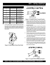
The right spider’s speed is adjusted by changing the length
of the connecting rod on the pump actuation levers (Figure
16, Page 17). This rod is basically a turnbuckle. Rotating it in
one direction increases the length and corresponding spider
speed. Rotating it the opposite direction decreases the length
and spider speed. The right spider’s speed should be within 3
rpm of the left.
A good starting point in the adjustment process is to adjust
the rod such that both spiders begin to rotate at the same time
when the foot pedal is slowly depressed. This will, generally,
get the speeds fairly close. Close enough for use if instrumen-
tation is unavailable (i.e. on the job site). From this point on,
some form of instrumentation is required to verify that the right
spider speed is within the tolerance specified above. A strobe
or magnetic pickup type speed indicator is recommended to
verify the speeds.
The speeds should be adjusted on a dry concrete floor with
the blades pitched flat. Units with a Kubota engine should be
set at 155-160 rpm with the engine at full speed. Units with a
B&S-Dihatsu (Vanguard) engine should be set at 145-150 rpm
with the engine at full speed.