


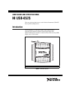

© National Instruments Corporation 5 USB-6525 User Guide and Specifications
Signal Descriptions
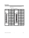
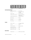
Table 2 describes the signals available on the I/O connectors.
Digital I/O
USB-6525 has eight channel-to-channel optically isolated inputs,
P1.<0..7>, and eight channel-to-channel optically isolated solid-state relay
outputs, P0.<0..7>. P1.7/PFI 0 can also function as a 32-bit counter. Refer
to the Event Counter section for more information about the counter.
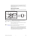
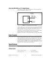
Optically Isolated Inputs
The USB-6525 provides eight channels of isolated digital inputs. These
inputs consist of an optocoupler, a depletion-mode MOSFET-based
current-limiting circuit, and Schottky diode.
Each channel has its own positive and negative terminals. The input range
on the channels is –60 VDC to +60 VDC.
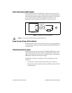
Sensing DC Voltages
The USB-6525 detects a wide range of DC signals, from TTL-like logic
levels to DC power supply levels up to 60 V.
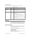
Table 2. Signal Descriptions
Signal Name Direction Description
P0.<0..7>A/B Output Solid-state relay 60 VDC/30 Vrms (42.4 V
pk
) output
P1.<0..6>+/– Input ±60 VDC digital input.
P1.<0..6>+ corresponds to the positive input terminal.
P1.<0..6>– corresponds to the negative input terminal.
P1.7+/– or PFI 0+/– Input This channel is configurable as either a digital input or
an event counter.
Digital Input Signal—±60 VDC digital input.
P1.7+ corresponds to the positive input terminal.
P1.7– corresponds to the negative input terminal.
CTR—As a counter, this signal can be used as an event
counter input source.
PFI 0+ corresponds to the positive counter terminal.
PFI 0– corresponds to the negative counter terminal.