


© National Instruments Corporation 9 USB-6525 User Guide and Specifications
Using the USB-6525 as a TTL Output Device
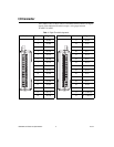
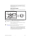
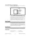
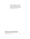
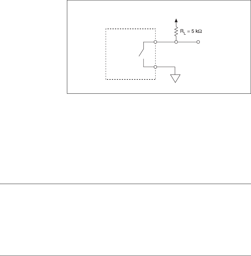
Figure 9 shows a signal connection example for a TTL-level application
with an external supply voltage of +5 V.
Figure 9. TTL Device Signal Connection Example
When the SSR is open, a small amount of current flows through R
L
and the
output voltage is close to 5 V, a logic high. When the SSR is closed, current
flows through R
L
and the output voltage is close to 0 V, a logic low.
Choose an R
L
value small enough to provide the necessary source current
but large enough to reduce sink current and to avoid consuming
unnecessary power. Many TTL-level applications use an R
L
value of 5 kΩ.
Event Counter
You can configure PFI 0 (an alias to P1.7) as the source for a 32-bit counter.
In this mode, the device counts low to high transitions on P1.7. The counter
can be armed and disarmed and the count can be read or reset through
software. For more information about event timing requirements, refer to
the Specifications section. Refer to your software documentation for more
information about counter programming techniques.
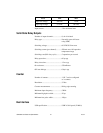
Specifications
The following specifications are typical at 25 °C, unless otherwise noted.
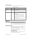
Isolated Inputs
Number of input channels...................... 8, ch-ch isolated
Input voltage range................................. –60 VDC to 60 VDC
V
OUT
Isolated
Ground
To External
+5 V Supply
P0.
x
A
P0.
x
B
USB-6525