


© National Instruments Corporation 7 USB-6525 User Guide and Specifications
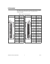
Solid-State Relay (SSR) Outputs
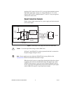
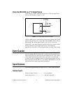
You can connect loads to the USB-6525. Connect the load to one of the
leads of the power source. Connect either the P0.xA or the P0.xB terminal
to the load and the other terminal to the other lead of the AC or DC power
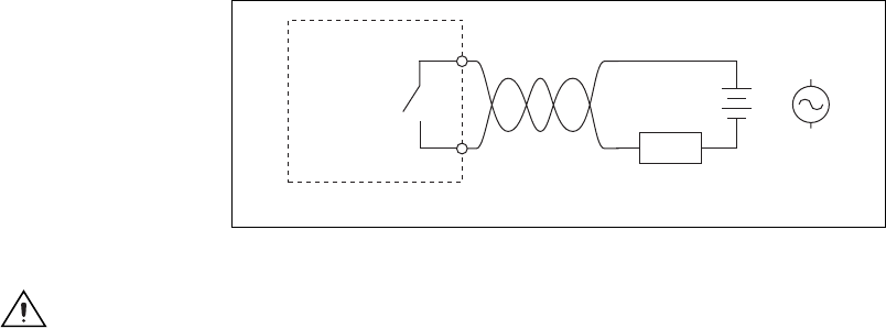
source. Figure 6 shows a possible configuration where the load is
connected to the P0.xB terminal and the DC or AC power source.
Figure 6. Connecting a Load to the USB-6525
Caution
Use twisted-pair field wiring to reduce EMC noise.
Power-On and Power-Off Conditions
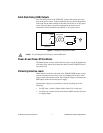
The default power-on state of the solid-state relays is open. By default, the
solid-state relays remain open when the chassis and the USB-6525 device
are powered off.
Protecting Inductive Loads
When inductive loads are connected to the USB-6525 SSR outputs, a large
counter-electromotive force may occur at switching time because of the
energy stored in the inductive load. These flyback voltages can damage the
SSR outputs and/or the external power supply.
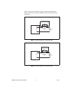
Limit flyback voltages at your inductive load by installing one of the
following:
• For DC loads—Install a flyback diode within 18 in. of the load.
• For AC loads—Install a metal oxide varistor (MOV) rated for 30 Vrms
or slightly higher.
+
_
or
AC
USB-6525
P0.
x
A
P0.
x
B
Load
Twisted-Pair
Wiring