


USB-6525 User Guide and Specifications 6 ni.com
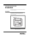
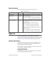
Applying a DC voltage of at least 3.2 V across two input terminals registers
logic high. Applying no voltage or a voltage difference of 1 V or less
registers logic low. DC voltages between 1 V and 3.2 V may not register a
consistent or usable value.
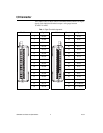
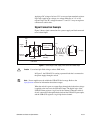
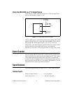
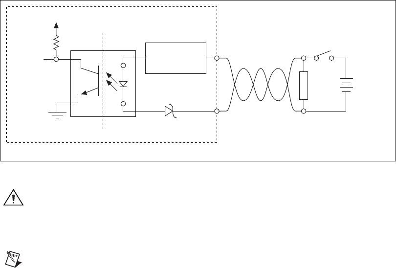
Signal Connection Example
Figure 5 shows signal connections for a power supply and load connected
to an isolated input.
Figure 5. Connecting a Power Supply and Load to the Isolated Input
Caution
Use twisted-pair field wiring to reduce EMC noise.
In Figure 5, the USB-6525 is sensing a powered load that is connected to
the power supply through a switch.
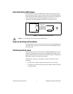
Note Power supplies must be within the USB-6525 device range. Refer to the
Specifications section for information about these ranges.
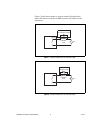
When the switch is open, no current flows through the load and no voltage
is applied to the load or to the USB-6525 input. The digital logic of the
USB-6525 then registers a logic low for the channel. When the switch is
closed, current flows through both the load and the USB-6525 optocoupler,
and the USB-6525 registers a logic high for the channel.
Isolation
Digital
Logic
Computer
Ground
USB-6525
P1.
x
+
P1.
x
–
MOSFET-Based
Current-Limiting
Circuitry
Schottky
Load
+
_
Twisted-Pair
Wiring
Vcc
Vsupply