


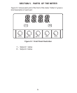
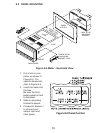

5.2 REAR OF THE METER (Continued)
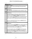
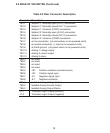
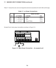
Table 5-2 Rear Connector Description
Connector Description
TB1-1 Setpoint 1: Normally open (N.O.1) connection
TB1-2 Setpoint 1: Normally closed (N.C.1) connection
TB1-3 Setpoint 1: Common (COM1) connection
TB1-4 Setpoint 2: Normally open (N.O.2) connection
TB1-5 Setpoint 2: Normally closed (N.C.2) connection
TB1-6 Setpoint 2: Common (COM2) connection
TB1-7 ac line connection (no connections on dc-powered units)
TB1-8 ac neutral connection (+ Input on dc-powered units)
TB1-9 ac Earth ground (-dc-power return on dc-powered units)
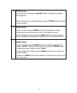
TB1-10 Analog 1 voltage output
TB1-11 Analog 2 current output
TB1-12 Analog 3 return
TB2-1 not used
TB2-2 not used
TB2-3 not used
TB2-4 not used
TB2-5 +E1: Positive excitation (current source)
TB2-6 +S1: Positive signal input
TB2-7 -S1: Negative signal input
TB2-8 -E1: Negative excitation
TB5-1 Isolated Analog Voltage Output
TB5-2 Isolated Analog Current Output
TB5-3 Isolated Analog Output Return
J1-1 Transistor Logic Output (positive)
J1-2 Transistor Logic Output (negative)
9