


iii
List of Figures
Figure Page
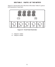
Figure 5-1. Front-Panel Illustration . . . . . . . . . . . . . . . . . . . . . . . . . . . . . . . .5
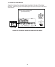
Figure 5-2. Connector Label (AC-Powered and DC-Powered Detail) . . . . . . .8
Figure 6-1. Main Board Power Jumpers (W1, W2, W3) . . . . . . . . . . . . . . . .11
Figure 6-2. Main Board Jumper Positions (6 S2 Pins) . . . . . . . . . . . . . . . . .11
Figure 6-3. Upper Option Board Installation . . . . . . . . . . . . . . . . . . . . . . . . .13
Figure 6-4. Meter - Exploded View . . . . . . . . . . . . . . . . . . . . . . . . . . . . . . .14
Figure 6-5. Panel Cut-Out . . . . . . . . . . . . . . . . . . . . . . . . . . . . . . . . . . . . . .14
Figure 7-1. 2-Wire RTD Input Connection . . . . . . . . . . . . . . . . . . . . . . . . . .15
Figure 7-2. 3-Wire RTD Input Connection . . . . . . . . . . . . . . . . . . . . . . . . . .15
Figure 7-3. 4-Wire RTD Input connection . . . . . . . . . . . . . . . . . . . . . . . . . .15
Figure 7-4. Main Power Connections - AC Powered Unit . . . . . . . . . . . . . . .15
Figure 7-5. Main Power Connections - DC Powered Unit . . . . . . . . . . . . . . .16
Figure 7-6. Analog Output Connections . . . . . . . . . . . . . . . . . . . . . . . . . . . .17
Figure 7-7. Relay Output Connections. . . . . . . . . . . . . . . . . . . . . . . . . . . . .17
Figure 7-8. Transistor Output Connections. . . . . . . . . . . . . . . . . . . . . . . . . .18
Figure 7-9. Isolated Analog Output Connections. . . . . . . . . . . . . . . . . . . . . .18
Figure 16-1. Proportional Band . . . . . . . . . . . . . . . . . . . . . . . . . . . . . . . . . .30
Figure 25-1. Meter Dimensions . . . . . . . . . . . . . . . . . . . . . . . . . . . . . . . . . .51
List of Tables
Table Page
Table 2-1. Accessories and Add-Ons . . . . . . . . . . . . . . . . . . . . . . . . . . . . . .2
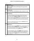
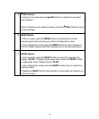
Table 5-1. Front Panle Part Description . . . . . . . . . . . . . . . . . . . . . . . . . . . . .6
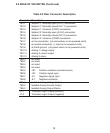
Table 5-2. Rear Connector Description . . . . . . . . . . . . . . . . . . . . . . . . . . . . .9
Table 6-1. S3 Jumper Functions . . . . . . . . . . . . . . . . . . . . . . . . . . . . . . . . .12
Table 7-1. Main Power Connections - AC Powered Unit . . . . . . . . . . . . . . .16
Table 21-1. Display Messages . . . . . . . . . . . . . . . . . . . . . . . . . . . . . . . . . .39
Table 22-1. Menu Configuration . . . . . . . . . . . . . . . . . . . . . . . . . . . . . . . . .40
Table 23-1. Front Panel Displays . . . . . . . . . . . . . . . . . . . . . . . . . . . . . . . .42
Table 23-2. Run Mode Displays . . . . . . . . . . . . . . . . . . . . . . . . . . . . . . . . .45
Table 24-1. Setpoint Configuration Displays . . . . . . . . . . . . . . . . . . . . . . . .46
Table 26-1. Factory Preset Values . . . . . . . . . . . . . . . . . . . . . . . . . . . . . . .52