


1-6 Introduction
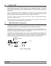
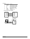
1.8 Termination Bus
In order to avoid signal reflections on the bus, each bus segment has to be blanked off at its physical beginning
and at its end with the characteristic impedance. A termination resister (Rt) is installed for this purpose. The Rt
value - 120Ω ± 2% is recommended, and the detailed connection of Rt can be referred from the “Terminator
Connection” diagram below.
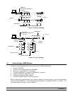
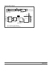
Terminator Connection
Host
Data+
Data-
120 ohms
Data+
Data-
120 ohms
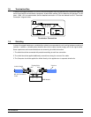
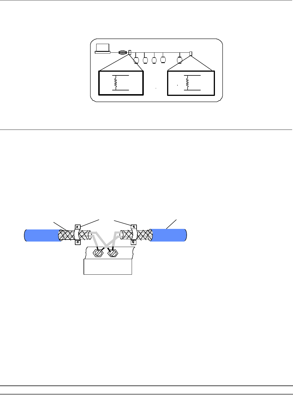
1.9. Shielding
In case of increased interference, a shielded bus cables is recommended to use for wiring between module and
modules. In addition, a shielding also should be done for the cable of power supply and for the signal cables.
Some experiences and recommendations are concerning for shield connection.
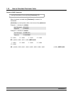
1. The shield should be connected with protective earthing at each bus connection.
2. The shield should be applied additionally several times along the course of the cable.
3. The Computer should be applied the shield directly to the appliance or to separate shield rails.
DA
TA
+
DA
TA
-
EarthingPoint
RS-485 Connection
Cable
OMR-Module
Isolation
braided shield