


4 Pelco Manual C521M (6/95)
4.2 AZL METER ADJUSTMENT
4.2.1 Preliminary Remarks
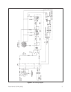
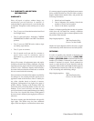
Figure 3 is a diagram of the internal wiring (minus power
supplies, etc.) of that part of the AZL unit related to
meter adjustment. Shown there are the full and center
scale pots for pan and tilt on the AZL as they would be
wired to the respective position feedback pots on a Pelco
P/T1250DC/PP. Interconnections between the two units
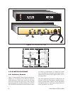
OFF
ON
360
0
0
0
180
0
PAN
TILT
0
0
+35
0
-35
0
+90
0
-90
0
5K
5K
POT
POT
POT
POT
1K
1K
F1
AC
AC
OUTLET
INPUT
LOCKING
NUT
OUTPUT
PAN
TILT
POT
ADJ
SCREW
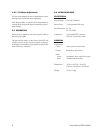
Figure 3. AZL Front and Rear Views
Figure 4. AZL Wiring Interface to P/T
are shown as circled numbers. As shipped, the pan/tilt
unit is mechanically configured to be resting at hori-
zontal in the tilt position and at approximately 180
°
in
the pan position.
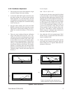
The meter adjustment procedure for both the pan and
tilt meters follows the same method. Assuming you have
already performed the connector and pot adjustments
indicated in Section 4.1, the step-by-step procedure for
meter adjustment is as follows:
+
–
+
–
AZL
5K
TILT
1K
5K
PAN
1K
10
10
2
2
99
11 11
PT1250DC/PP
FEEDBACK B+
TILT FEEDBACK
PAN FEEDBACK
FEEDBACK
COMMON