


10 C1649M (1/06)
REAR PANEL
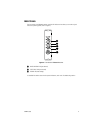
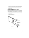
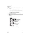
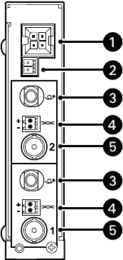
Connections to the FR8302A receiver are made to the rear panel of the module (refer to Figure 3).
Figure 3. Rear Panel of FR8302A Receiver
NOTE: For each channel, the FR8302A receiver provides two video output connectors: one UTP
connector and one BNC connector. For each channel, only one of the video output connectors can be
used at one time.
For additional information about rear-panel connections, refer to the Installation section.
ᕡ RACK POWER/ALARM CONNECTOR, 4-pin connector for power/alarm connection of rack-
mounted module
ᕢ STANDALONE POWER CONNECTOR, 2-pin connector for power connection of standalone
module; removable mating connector with screw terminals (not shown)
ᕣ
FIBER OPTIC CONNECTOR (per channel), ST or FC (dependent on FR8302A model)
ᕤ VIDEO OUT UTP (UNSHIELDED TWISTED PAIR) CONNECTOR (per channel), 100-ohm
differential analog video output; 2-pin connector; removable mating connector with spring-
cage terminals (not shown)
ᕥ
VIDEO OUT BNC CONNECTOR (per channel), 75-ohm analog video output