


14 C1649M (1/06)
Troubleshooting
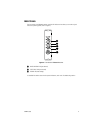
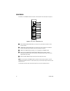
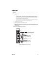
LED indicators on the front panel of the FR8302A receiver (refer to Figure 2) allow you to monitor
signal status and operating power. Table A provides information about the front-panel indicators and
associated troubleshooting guidelines.
NOTE: For troubleshooting information indicated by the LEDs on the associated FT8301A/FT8301
transmitter, refer to the manual supplied with the transmitter.
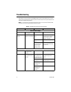
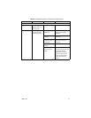
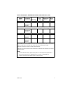
Table A. Troubleshooting with Front-Panel Indicators
Indicator Color Meaning Possible Cause Corrective Action
Power LED (Pelco badge)
Blue Pelco logo
lights.
Power is being applied
to the module.
– No action required.
Blue Pelco logo does
not light.
Power is not being
applied to the module.
Power connection is
faulty.
Check power connection.
If module is rack mounted,
reseat module or power
supply as necessary.
Power supply has
failed.
Replace power supply.
Loss of power occurs
due to tripped circuit
breaker(s), blown
fuse(s), or faulty
electrical service.
Check circuit breaker(s),
fuse(s), or electrical service
as necessary.
Video Present LED
Green Incoming video signal
is present on the
channel.
– No action required.
Red Incoming video signal
is not present on the
channel.
Optical signal is not
being received from
the transmitter. Optic
Fault LED is also red.
Refer to the Optic Fault LED
troubleshooting section
below.
Video source is not
powered on.
Check power connection to
the video source.
Video source is not
connected to the
transmitter.
Check BNC connections.
Coaxial cable
connected to the
transmitter is
defective.
Replace cable.
(Continued on next page)