


C1649M (1/06) 13
CONNECTIONS
Connections to the FR8302A receiver are made on the rear panel of the module and consist of the
following:
• Power connection
NOTES:
– A 12 VDC or 24 VAC power supply can be used to power the receiver when used as a
standalone module. A 12 VDC power supply is provided. If a 24 VAC power supply is
used, the power supply must be a Listed Direct Plug-In Power Unit marked as Class 2
and rated as 24 VAC, 200 mA (minimum output).
– In extreme temperature conditions, it is recommended that an industrial-rated outdoor
power supply such as the Pelco WCS1-4 power supply be used.
• Fiber connection (per channel)
• Video output connection (UTP or BNC per channel)
NOTE: When connecting to the UTP connector, it is recommended that solid UTP wire rather
than stranded UTP wire be used. If stranded UTP wire is used, it is recommended that you tin
the stranded wire.
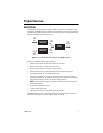
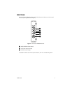
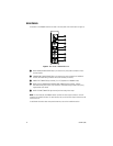
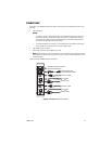
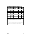
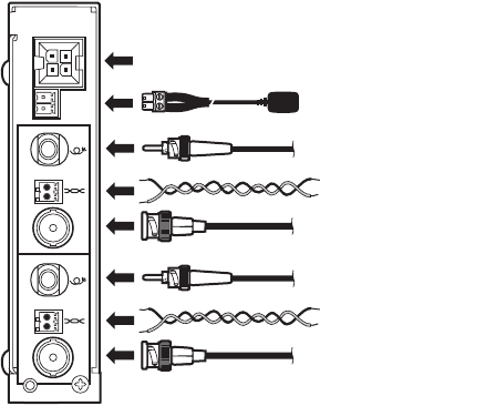
Figure 5 illustrates FR8302A receiver connections.
Figure 5. FR8302A Receiver Connections
POWER CONNECTION
FOR STANDALONE MODULE
FIBER OPTIC CABLE
COAXIAL CABLE
UTP CABLE
OR
FIBER OPTIC CABLE
COAXIAL CABLE
UTP CABLE
OR
POWER/ALARM CONNECTION FOR
RACK-MOUNTED MODULE
+
-
+
-
2
1