


3
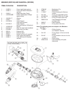
(9) Before removing the exhaust valve (Item 12) from the case, bend it over as far as it will go from the
top, bottom, left and right sides. If it fails to snap back quickly, and does not lie perfectly flat against the case,
the valve should be replaced. If it does snap back satisfactorily, remove it and inspect the sealing edges. If
they appear smooth, and the locking tab on the nipple is good, the valve can be reused.
(10) Remove the lever support from the inside of the case (Item 13).
(11) Normally, you will simply need to change the poppet stem seat insert (Item 9) to restore the second
stage to maximum performance. To change the stem seat insert (Item 9), leave the lever assembly together.
With a penknife or similar object, carefully remove the old seat insert. Put the new seat insert on a clean flat
surface and lower the poppet cavity (from which the old seat insert was removed) over the new seat insert.
(12) If parts of the lever assembly (stem, spring, lever, etc.) need to be replaced, take apart the assembly
with the Sherwood stem socket tool (p/n TL124). Clamp the stem socket tool in a bench vice. Insert the square
head of the poppet stem into the tool. With a Phillips screwdriver, loosen the screw (Item 3) that holds
the assembly together
two turns only.
(13) Re-install the orifice housing onto the lever support (without the case) turning the two parts together
firmly by hand. This will cause the poppet (Item 8) to be pushed out farther than normal by the orifice. This in
turn will cause the lever to go limp.
NOTE: If only the lever (Item 5) is to be replaced, do not totally remove the screw. You can now remove
the lever from under the washer and replace it with a new lever. If other parts such as the spring (Item 7) are
to be replaced, remove the screw (Item 3) fully. Then remove the orifice housing from the lever assembly to
get these parts out.
(14) Rinse all plastic and silicone parts in clean fresh water, and then blow the parts dry with compressed
air to remove any sand and dust particles.
(15)
If necessary, clean all metal parts of the second stage in an ultrasonic cleaner or cleaning solution.
Remove the O-rings before cleaning any metal parts; most cleaning solutions are damaging to the O-ring
material. See page 7 for recommendations on cleaning solutions.
NOTE: If you use an ultrasonic cleaner to clean the adjustable orifice (Item 18), use a plastic container to
prevent the orifice from vibrating against other metal parts which could damage the orifice seal.
(16) Inspect the case (Item 13) for any cracks. Look particularly closely at the area where the orifice
housing and the lever support clamp down. Replace the case if any cracks are found.
(17) Inspect the orifice's (Item 18) sealing cone (where the poppet insert seals) for any nicks, scratches, or
corrosion. Corrosion or minor scratches can be polished out using a fine-grit rubberized polishing stick or a
clean new pencil eraser.
Do not apply heavy pressure when rotating the polishing stick. Stop polishing immediately after the
corrosion or scratch disappears. Blow all dust and debris out of the orifice housing with clean compressed air.
NOTE: Prior to this point, you should have cleaned and inspected all parts, following proper servicing
procedures.
Do not continue until this has been done.
ASSEMBLY
(1) Re-install the cleaned and lubricated O-ring (Item 19) onto the adjustable orifice (Item 18). Install the
adjustable orifice back into the orifice housing. Push it in with your finger as far as it will go.
(2) Install the exhaust valve (Item 12) into the case by inserting the nipple into the small hole from the
outside of the case. Reach inside the case and pull the nipple firmly with the fingers until you hear or feel it
"click" into place. Inspect the exhaust valve to see that it is properly seated.