


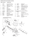


(3) Snap the exhaust grid (Item 10) back into its slots. Make sure it is properly seated.
(4) Install the lever assembly into the case.
(5) Screw the orifice housing (Item 16) onto the threads of the lever assembly. Hold the case (Item 13) in
one hand. Use a 3/4" wrench on the orifice housing. Tighten the orifice housing and the lever assembly
together snugly (70 in. lbs.).
Note: Do not allow lubrication (grease on fingers, or silicone over-spray) to get on the case (Item 13), the
diaphragm (Item 2), or the exhaust valve (Item 11) as it may cause slippage or deterioration of these parts.
Note: If the unit is a SR3209 Shadow+, the O-rings (Items 24 & 25) should now be lubricated and
replaced onto the orifice housing (Item 23). The larger of the two O-rings goes on closest to the case (Item
13). Install the short hose assembly onto the swivel (Item 26). Lubricate the inner bore of the swivel. Re-install
the swivel back onto the orifice housing.
Note: The following steps (5-8) are included here for continuity. They must be performed after the regulator
second stage is adjusted (see "Set-Up of Second Stage," page 4).
(6) Install the diaphragm (Item 2) into the case so that it sits evenly on the ledge.
(7) Install the cover (Item 1) onto the case by sliding it carefully and firmly into place.
(8) Install the four screws (Item 12) that hold the cover onto the case using a # 10 Torx screwdriver
(Sherwood Tool TL117) or a small slotted screwdriver.
CAUTION! DO NOT OVER-TIGHTEN. These screws are threading into plastic, which will hold well in
service but can be stripped if over-tightened.
(9) Install the mouthpiece (Item 15) and mouthpiece tie (Item 14).
SET- UP
NOTE: For the following adjustments, remove the cover and diaphragm.
(1) Install Sherwood's in-line adjusting tool (p/n TL102) between the orifice housing (Item 16) and the hose
assembly (Item 20). Use the tool to screw the adjustable orifice (Item 18) clockwise. Watch the end of the lever
(Item 5) as you do this. As soon as the tip of the lever begins to drop, stop turning the tool.
NOTE: The slight amount of friction this operation produces between the orifice and the stem seat will not
harm the stem seat.
(2) Attach the second stage to its accompanying overhauled and properly adjusted first stage, and mount
on an air tank filled to between 2700 and 3500 psig.
(3)
Slowly turn on the tank valve. If you hear any leaks, determine the location of the leak, shut the air
off, and repair the leak as necessary.
(4) Turn on the air. Use the in-line adjusting tool to turn the adjusting orifice (Item 18) counter-clockwise
until you hear a slight hissing. Then turn the adjusting orifice clockwise just enough to stop the hissing.
NOTE: A slight clockwise turn past the point where the hissing just stops will reduce wear and tear on
regulators used heavily in rental or training situations.
(5) Depress the lever assembly in the second stage five or six times to get the internal parts seated in their
proper positions. Listen for any hissing. Adjust if necessary.
4