Series 830/840/860 Instruction Manual Chapter 2 Installation
IM-83/84/86-H 2-5
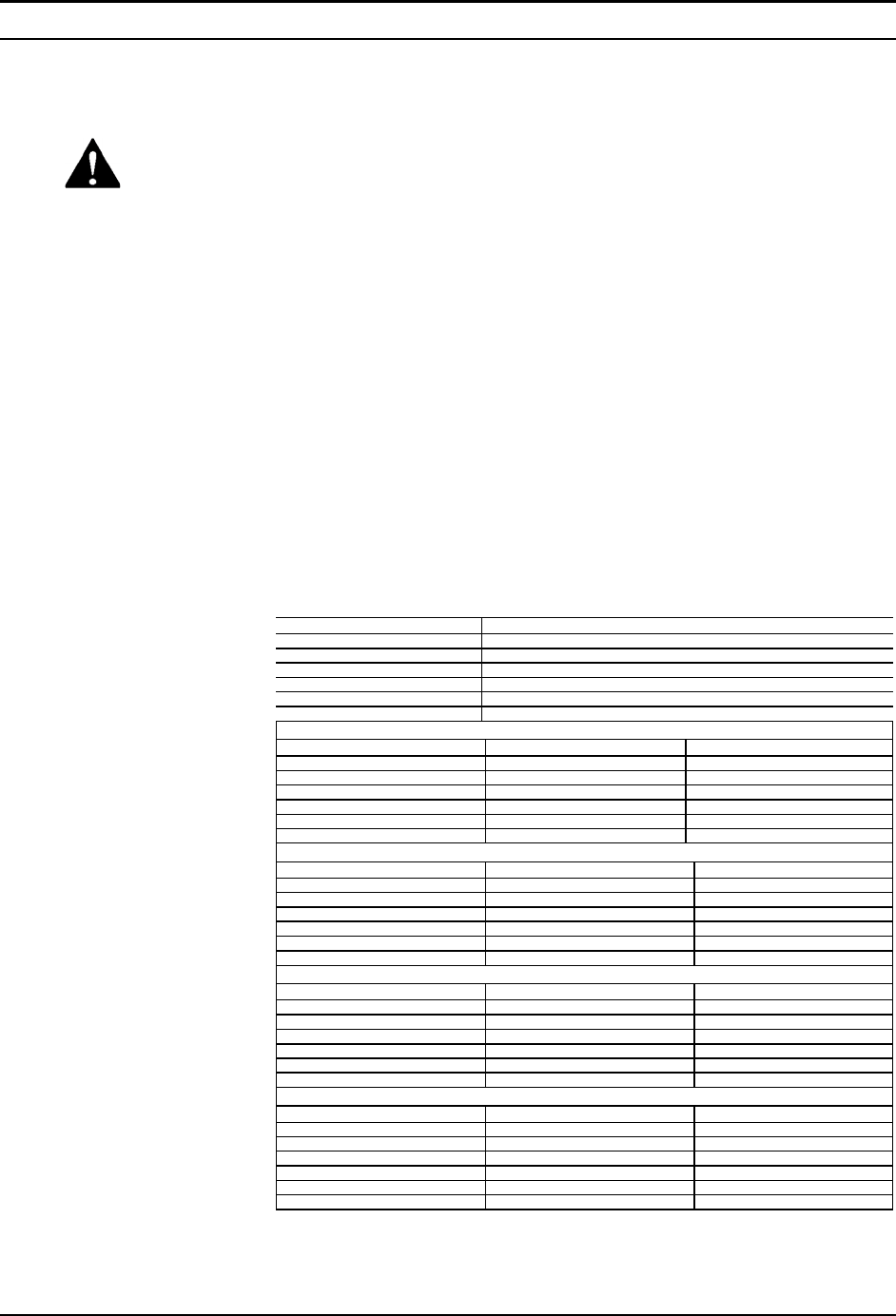
Wiring the Transducer
Side-Trak and Auto-Trak transducers require a +15, 0, –15 VDC power
supply and a readout device. Additionally, controllers require a set
point input (0-5 VDC standard, 4-20 mA optional). Transducers are
connected to the power supply, output signal and set point control
through either a
20-pin card-edge connector or 15-pin D-connector. Motor-operated ro-
tary valves use a 10-pin circular connector. Wiring instructions are
given for each type of connector on the following pages. If you are re-
placing another manufacturer’s transducer with a Sierra product, see the
factory-supplied wiring supplement for instructions specific to your in-
stallation.
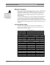
Recommended Wire Gauges
Using the correct wire gauge for cabling runs to transducers en-
hances system reliability. For cable runs over 150 feet (46 m), con-
sider using a local power supply.
Model 830/860M (all ranges)
Distance in feet
Recommended Min. Wire Gauge
25
34
50
32
100
28
200
26
300
24
500
22
Model 840/860C Low Flow, 15 Volt Valve
Distance in feet
COM & –15 VDC Pins
All Others
25
30
34
50
28
32
75
26
28
100
26
28
125
24
26
150
24
26
Model 840/860C Low & Medium Flow, 30 Volt Valve
Distance in feet
COM & –15 VDC Pins
All Others
25
26
34
50
24
32
75
22
28
100
22
26
125
20
26
150
20
26
Model 840/860C High Flow, 30 Volt Valve
Distance in feet
+15 & –15 VDC Pins
All Others
25
22
34
50
20
32
75
18
28
100
16
26
125
16
26
150
14
26
Model 840/860C Motor-Operated Rotary Valve
Distance in feet
+15, –15 & COM Pins
All Others
25
26
34
50
24
32
75
22
28
100
22
26
125
20
26
150
20
26
Warning!
Follow National Electric
Code or your local code
safety practices when wir-
ing or connecting this unit
to a power source. Only
qualified personnel should
wire the transducer.


