


GP Series Portable Chillers Chapter 3: Installation 16 of 73
installation. If there is no pressure, leak test the unit and repair before installing the
interconnecting refrigerant piping. Read this entire section before installation.
Note: Piping should be type “L” or type “K” refrigerant grade copper tubing only.
Proper sizing and installation has a significant effect on system performance,
reliability, and safety.
Interconnecting Refrigerant Piping. The chiller and condenser refrigerant lines are
terminated with a cap and brazed closed. Use a tube cutter to remove caps.
Caution! Do not use a saw to remove the end caps because this will allow copper chips to
contaminate the system.
A certified refrigeration contractor need only to install the interconnecting refrigerant piping
between the chiller and the outdoor air-cooled condenser. This piping must be properly sized,
type “L” or type “K” refrigerant grade tubing, high temperature brazed, Install a customer
supplied 650 psi approved refrigerant relief valve in the discharge line at the condenser,
following all codes.
When brazing copper joints, flow dry nitrogen through the system to prevent carbon/scale
formation, which causes contamination. Isolate the refrigerant lines from the building,
preventing transfer of line vibration to the structure. Do not secure the lines rigidly.
Leak check and evacuate the system down to 400 microns. A decay of 50 microns after one
hour is acceptable.
Warning! To prevent injury or death due to explosion and/or inhalation of phosgene gas,
purge system thoroughly while brazing refrigerant piping connections. Use a
pressure regulator in the line between the unit and the high-pressure nitrogen
cylinder to avoid over-pressurization and possible explosion.
System Configuration. The system can be configured in any of the arrangements shown on
page 59 of the Appendix. The configuration and distance between the chiller and the
condenser affects pipe size, refrigerant charge, oil return, and oil charge. Therefore there are
limitations that must be adhered to for reliable and optimal operation.
• Leaving water temperature affects discharge line size. Be sure to inform the installing
contractor of the leaving water temperature range in which the chiller will be operating
• The total distance between the chiller and condenser must not exceed 200 feet or 300
equivalent pipe feet
• Discharge line risers cannot exceed an elevation difference greater than 100 feet
without a 2% efficiency decrease.
• Refer to page 59 of the Appendix for the location of traps.
• Refrigeration lines must not be crossed, i.e., chiller liquid lines are to be piped to
condenser liquid lines.
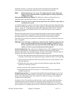
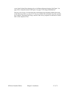
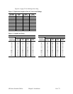
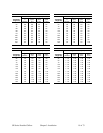
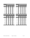
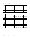
Sizing Refrigerant Lines. To determine field installed liquid and discharge line sizes, first
establish the equivalent length of pipe for each line, valve, and elbow. Chiller capacity and
leaving water temperature range is also required. See Figure 2 on page 18 for lengths of
refrigerant valves and fittings.
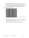
Liquid Line Sizing. The liquid line should be sized as small as possible while maintaining
acceptable pressure drop to minimize the refrigerant charge. Liquid line risers must not
exceed 15 feet from the base of the air-cooled condenser. Horizontal runs do not require a
pitch. Insulation is not required unless the line is installed in a high ambient area, i.e., boiler