


GP Series Portable Chillers Chapter 7: Appendix 60 of 73
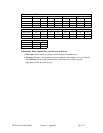
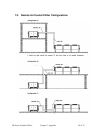
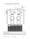
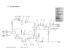
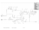
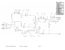
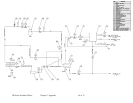
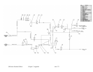
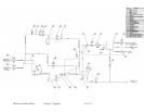
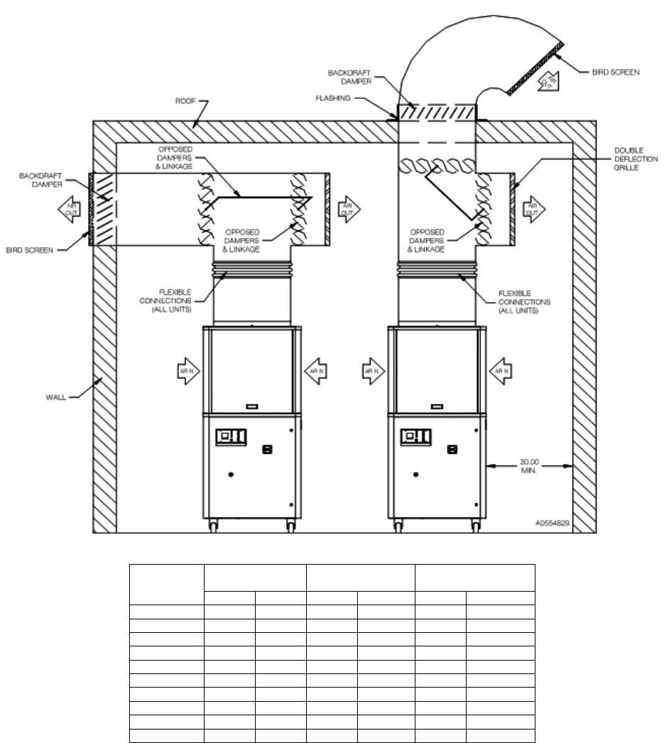
7-6 Typical Ductwork for Air-Cooled Chillers
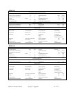
Fan
60 Hz Discharge
air volume
50 Hz Discharge air
volume
Model
HP kW CFM m
3
/min CFM m
3
/min
GPAC-20 0.5 0.4 4230 120 3525 100
GPAC-30 1.0 0.7 6343 180 5286 150
GPAC-40 1.0 0.7 8458 240 7048 200
GPAC-50 2.0 1.5 12687 360 10573 300
GPAC-70 (2) 1.0 (2) 0.7 16916 479 14097 399
GPAC-90 (2) 2.0 (2) 1.4 25374 718 21145 598
GPAC-105 (2) 2.0 (2) 1.4 25374 718 21145 598
GPAC-140 (3) 2.0 (3) 1.4 38061 1077 31718 898
GPAC-175 (3) 2.0 (3) 1.4 38061 1077 31718 898
GPAC-210 (4) 2.0 (4) 1.4 50748 1436 42290 1197
When locating your air-cooled portable chiller and designing its ductwork, note any potential high
temperature conditions when discharging into your building and any negative pressures with the building
when discharging air outside.
Notes: • Customer use of ductwork requires the high pressure fan option. • Allow 30” (77 cm) minimum
clearance around the chiller footprint to facilitate free passage of cooling air and service accessibility •
Size the ductwork for maximum capacity • Support ductwork from the building structure, not off of the