


5-14
SERIES3800/S120T (7045A-C3/7045A-CT) User's Manual
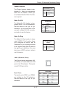
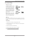
PW_ON Connector
The PW_ON connector is on pins 1
and 2 of JF1. This header should be
connected to the chassis power but-
ton. See the table on the right for pin
defi nitions.
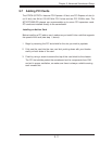
5-9 Connector Defi nitions
Required Connection
+12V 4-pin Power
Pin Defi nitions (JPW1)
Pins Defi nition
1 - 2 Ground
3 - 4 +12V
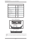
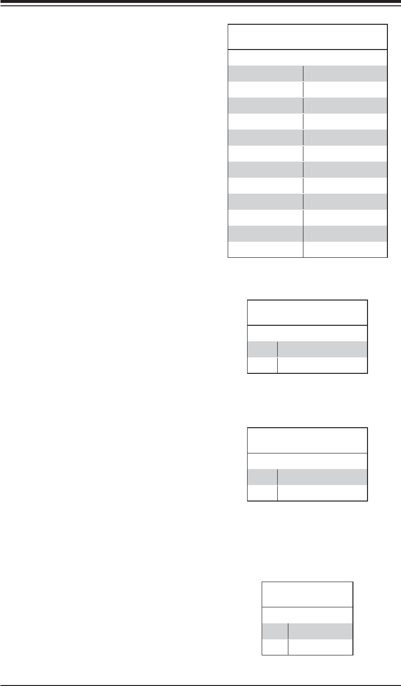
ATX Power 24-pin Connector
Pin Defi nitions (JPW3)
Pin# Defi nition Pin # Defi nition
13 +3.3V 1 +3.3V
14 -12V 2 +3.3V
15 COM 3 COM
16 PS_ON 4 +5V
17 COM 5 COM
18 COM 6 +5V
19 COM 7 COM
20 Res (NC) 8 PWR_OK
21 +5V 9 5VSB
22 +5V 10 +12V
23 +5V 11 +12V
24 COM 12 +3.3V
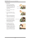
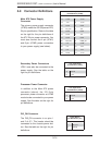
Power Button
Pin Defi nitions (JF1)
Pin# Defi nition
1 PW_ON
2 Ground
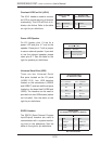
Secondary Power Connectors
JPW1 must also be connected to the
power supply. See the table on the
right for pin defi nitions.
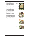
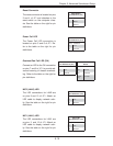
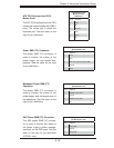
Main ATX Power Supply
Connector
The primary power supply connector
(JPW3) meets the SSI (Superset ATX)
24-pin specifi cation. Refer to the table
on the right for the pin defi nitions of
the ATX 24-pin power connector. You
must also connect the 4-pin (JPW1)
and 8-pin (JPW2) power connectors
to your power supply (see below).
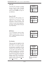
Required Connection
+12V 8-pin Power
Pin Defi nitions (JPW2)
Pins Defi nition
1 - 4 Ground
5 - 8 +12V
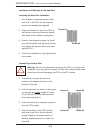
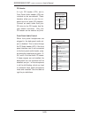
Processor Power Connector
In addition to the Main ATX power
connector (above), the 12V 8-pin
processor power connector at JPW2
must also be connected to your power
supply. See the table on the right for
pin defi nitions.