


5-16
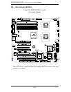
SERIES3800/S120T (7045A-C3/7045A-CT) User's Manual
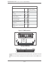
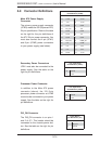
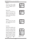
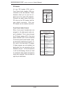
Fan Headers
There are eight fan headers on the
serverboard, all of which are 4-pin
fans. (Pins 1-3 of the fan headers
are backward compatible with the
traditional 3-pin fans.) See the table
on the right for pin defi nitions. The
onboard fan speeds are controlled
by Thermal Management (via Hard-
ware Monitoring) under the Advanced
Section in the BIOS. The default is
disabled. When using Thermal Man-
agement setting, please use all 3-pin
fans or all 4-pin fans.
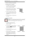
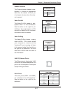
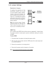
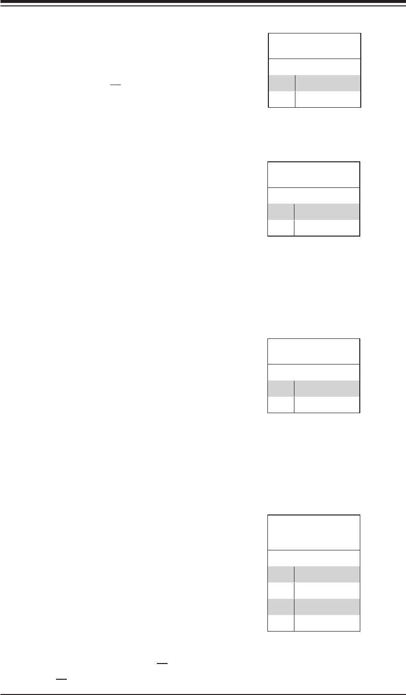
NMI Button
The non-maskable interrupt button
header is located on pins 19 and 20
of JF1. Refer to the table on the right
for pin defi nitions.
NMI Button
Pin Defi nitions (JF1)
Pin# Defi nition
19 Control
20 Ground
Fan Header
Pin Defi nitions
(FAN1-8)
Pin# Defi nition
1 Ground (Black)
2 +12V (Red)
3 Tachometer
4 PWM Control
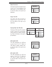
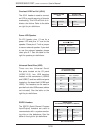
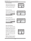
Power On LED
The Power On LED connector is lo-
cated on pins 15 and 16 of JF1 (use
JLED for a 3-pin connector). This
connection is used to provide LED
indication of power being supplied to
the system. See the table on the right
for pin defi nitions.
Power LED
Pin Defi nitions (JF1)
Pin# Defi nition
15 5V Stby
16 Control
Note: Fan 7 is for the CPU1
and Fan8 is for the CPU2
heat sink.
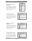
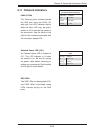
HDD LED
The HDD LED connection is located
on pins 13 and 14 of JF1. This LED
is used to display all IDE and SATA
activity. See the table on the right for
pin defi nitions.
HDD LED
Pin Defi nitions (JF1)
Pin# Defi nition
13 Vcc
14 HD Active