


6-8
SERIES3800/S120T (7045A-C3/7045A-CT) User's Manual
Installing Components in the 5.25" Drive Bays
The 7045A-C3/7045A-CT has two 5.25" drive bays. Components such as an extra
fl oppy drive, IDE hard drives or CD-ROM drives can be installed into these 5.25"
drive bays.
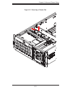
Removing the Empty Drive Bay
First power down the system.1.
Remove the top/left chassis cover to access the drive components.2.
With the cover off, remove the screws that secure the drive carrier to the 3.
chassis (one side only) then push the entire empty drive carrier out from the
back.
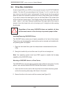
Adding a DVD/CD-ROM Drive
Remove the guide plates (one on each side) from the empty drive carrier 1.
and screw them into both sides of the DVD/CD-ROM drive using the holes
provided.
Slide the DVD/CD-ROM into the bay and secure it to the chassis with the 2.
drive carrier screws you fi rst removed.
Attach the power and data cables to the drive.3.
Replace the top/left chassis cover and restore power to the system.4.
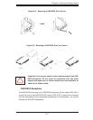
Adding an IDE or Floppy Drive
Install an IDE or fl oppy into one of the removed empty drive carriers 1. with the
printed circuit board side toward the carrier so that the drive's mounting holes
align with those in the carrier.
Secure the drive to the carrier with screws then slide the assembly into 2.
the bay and secure it to the chassis with the drive carrier screws you fi rst
removed.
Attach the power and data cables to the drive.3.
Replace the top/left chassis cover and restore power to the system.4.
Note: A red wire typically designates the location of pin 1. Drive carriers should
remain in any empty drive bays to maintain proper airfl ow within the chassis.