


149-072011 Model 2002 Vacuum Gauge Page 24 of 38
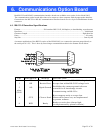
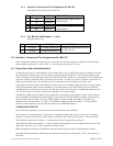
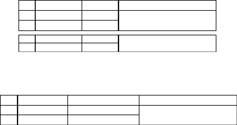
6.1.1. Interface Connector Pin Assignments for RS-485
(Full duplex-4 wire)(Jumper position 2-3).
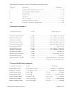
6.1.2. For RS-485 (Half Duplex – 2 wire)
(Jumper position 1-2).
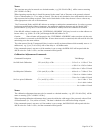
6.2. Interface Connector Pin Assignments for RS-232
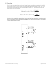
Note: an alternate method of connecting to a 2 wire bus is to leave the interface configured for full duplex
and externally connect pins 2 and 3 to the (+) bus and pins 4 and 8 to the (-) bus.
6.3. Operation of the Serial Interface
Communication with the serial interface of the Model 2002 is via an ASCII data string. In the RS-232 mode
the command message consist only of a command string and the terminator. The attention character and
address string are not required, but if they are used they MUST be valid. If all components of the ASCII data
string are valid the command will be accepted and executed. The RS-232 mode is sometimes referred to as
point-to-point mode since only one device may be connected to the controller at any given time.
A message to the Model 2002 in the RS-485 mode consists of an attention character followed by the address
string, the command string, and the terminator. If all components of the ASCII data string are valid the
command will be accepted and executed. The RS-485 mode is also referred to as multipoint mode since up
to 31 devices may be connected to the same controller in a network scheme.
The RS-485 address may be display on the model 2002 front panel (with software version 1.60 or higher).
Press the MODE switch until the units field is lit, press both the UP nad DOWN switches simultaneously.
The units light will now flash. Press the ZERO switch to display the RS-485 address (the address is
displayed in it’s decimal form). Use the UP or DOWN switch to modify the address. Use the MODE
switch to exit this function and save the new address into EEPROM memory.
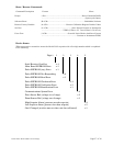
COMMAND SYNTAX
In the following examples of syntax codes, the special characters are explained:
The characters in square brackets [ ] represents a command string, either upper or lower case command
characters accepted. All characters must follow each other in the string with no spaces or other characters.
The characters within wavy brackets { } contain choices for the appropriate command.
The characters within the symbols < > are the common abbreviations for the one digit ASCII control codes
which they represent, (e.g. <CR> represents carriage return).
When entering more than one command in the same data string, they must be separated by a comma.
All command strings must be followed by the terminator character (carriage return <CR>, also known as
ENTER).
PIN MNEMONIC SIGNAL DESCRIPTION
2TX+Transmit +
8TX-Transmit -
3RX+Receive +
4RX-Receive -
Differential data signal levels to
the RS-485 bus
Differential data signal levels to
the RS-485 bus
PIN MNEMONIC SIGNAL DESCRIPTION
2 TX+/RX+ Transmit +/Receive+
8 TX-/RX- Transmit -/Receive -
Differential data signal levels to
the RS-485 bus