


149-072011 Model 2002 Vacuum Gauge Page 8 of 38
3. Front Panel Operation
3.1. Overall Functional Description
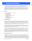
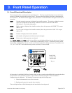
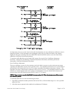
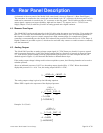
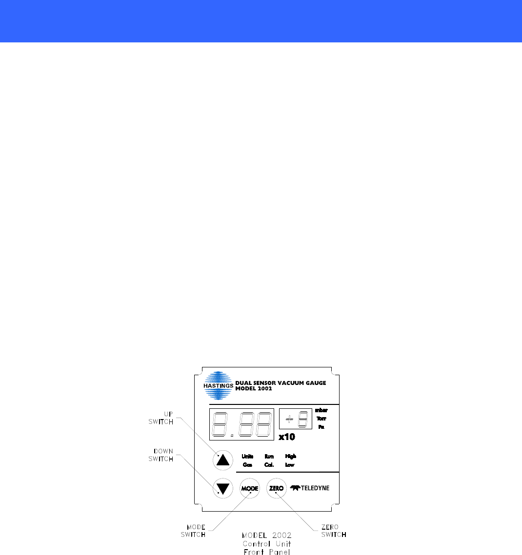
The front panel of the control unit is shown in Figure 3.1. The four circular blue buttons are used for the
selection of display readout and the input of data. The green data field displays the data as determined by
mode selection. The MODE switch toggles the control unit in a clockwise fashion among the six modes of
operation:
RUN Normal operation, pressure is displayed in scientific notation. The analog to digital converter
speed can be adjusted and the factory calibration can also be restored in this mode.
See Section 3.2 for further information.
HIGH High set point is displayed in scientific notation, above this pressure the HIGH TTL output
will be +5V.
LOW Low set point is displayed in scientific notation, below this pressure the LOW TTL output
will be +5V.
CAL Pressure is displayed and can be adjusted.
GAS Gas number is displayed and selection may be changed.
UNITS Units used to display pressure are selected.
In the RUN, HIGH, and LOW modes, it is possible to see the display indicate that the data is out of range.
Over range is indicated by X.XX x10- . Under range is indicated by 0.0 x10-. A measured pressure below
1x10⁻⁴ Torr is indicated by 0.0 x10+. In the case of an unconnected or faulty sensor(s), it is possible to see
“X”, “XX” OR “XX” See trouble shooting section (section 8) for more detail.
All six modes of the Model 2002 have features which can be accessed and modified after bypassing the front
panel interlock. The interlock is in place to prevent the accidental corruption of the instrument’s
configuration and calibration. The interlock is bypassed using the following steps:
1. Place the instrument in one of the six modes.
2. Simultaneously press the up and down switches.
The mode light will now flash indicating that the interlock has been bypassed.
®
Model 2002
Control Unit
Front Panel
Fig 3.1