


E6581315
15
Inverter → Computer
At time of broadcast communication of the binary mode, returning of data is not executed except for
the inverter to be returned (inverter number 00H) and when the inverter number is not matched. This
is because there will be a risk that the returned data may be deformed.
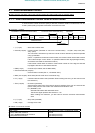
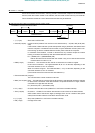
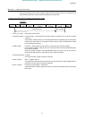
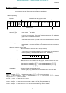
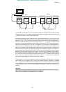
1) Normal processing
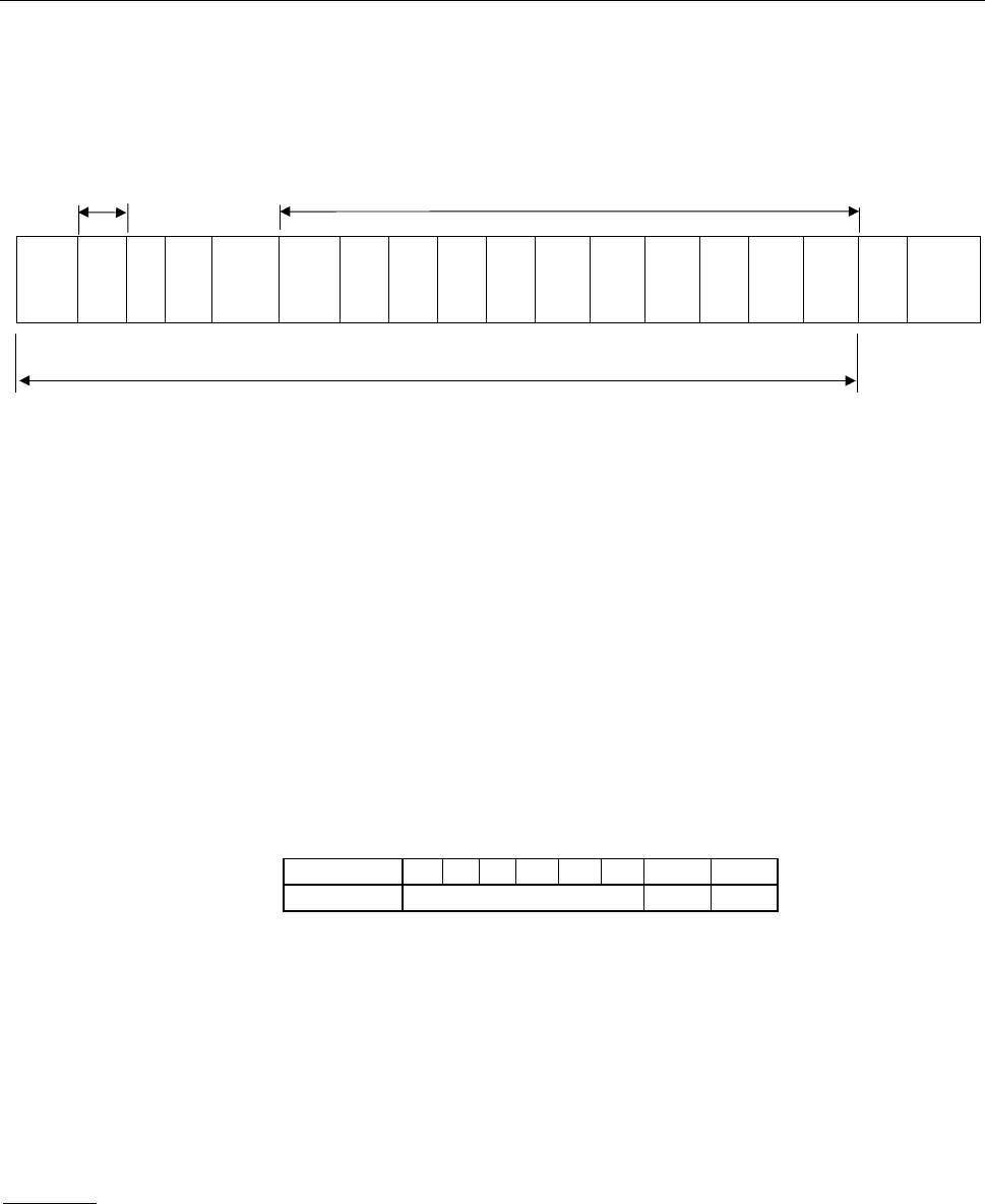
1. 2FH “/” (1 byte) Start code in binary mode
2. INV-NO (1Byte) Inverter number 00H to 3FH
If the inverter number matches up with that specified from the operation panel, data will
be returned from the inverter. If the inverter number does not match, the data will be
judged invalid and no data will be returned.
Communication data will be invalidated and data will not be returned either if the in-
verter number does not match. (Inverter number is considered matched if it is omitted
during reception)
3. CMD(1Byte) :‘Y’ (Block communication command [monitoring])
Lowercase letter ‘y’ during an inverter trip, including standing by for retrying and during
a trip.
4. Number of read data groups (1 byte)
: Return the number of data groups to be read (00H to 05H).
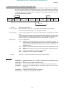
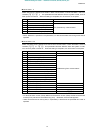
5. Write status (1 byte) : Return 00H to 03H.
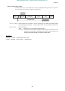
* Failing to write in the specified parameter in the number of write data groups, set “1”
in the corresponding bit for the parameter failed to write. (See below.)
6. Read data1 - 5 (2 bytes)
: Return according to the number of read data groups. “0000H” is returned as dummy
data if “0” is selected as a parameter.
Read data1: Data selected by . Read data2: Data selected by .
Read data3: Data selected by . Read data4: Data selected by .
Read data5: Data selected by .
7.SUM(1Byte) : Checksum (Cannot be omitted) 00H to FFH
Lower two digits (1 byte) of total sum from start code of return data to read data.
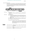
Example
(When set as follows: = (Command information 1), = (frequency command),
= (status information), = (output frequency), = (output current), = (output
voltage) and = (alarm information)
Computer → Inverter 2F 58 02 05 C4 00 17 70 D9
Inverter → Computer 2F 59 05 03 00 00 00 00 00 00 00 00 00 00 90 (When parameter is not set)
Inverter → Computer 2F 59 05 00 40 00 00 00 00 00 00 00 00 00 CD CD (When parameter is set)
Inverter → Computer 2F 59 05 00 64 00 17 70 1A 8A 24 FD 00 00 3D (During operation at 60Hz)
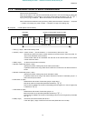
(3.5
bytes
Blank)
Start
Code
“/”
INV
No.
CMD
“Y”
Number
of Read
Data
Groups
Write
Status
Read
data1
high
Read
data1
low
Read
data2
high
Read
data2
low
Read
data3
high
Read
data3
low
Read
data4
high
Read
data4
low
Read
data5
high
Read
data5
low
SUM (3.5
bytes
Blank)
Checksum area
Omissible
Number of read data groups x 2 bytes
Bit Position 7 6 5 4 3 2 1 0
Data Type
efesotomasyon.com -Toshiba inverter,drive,servo,plc