E6581315
32
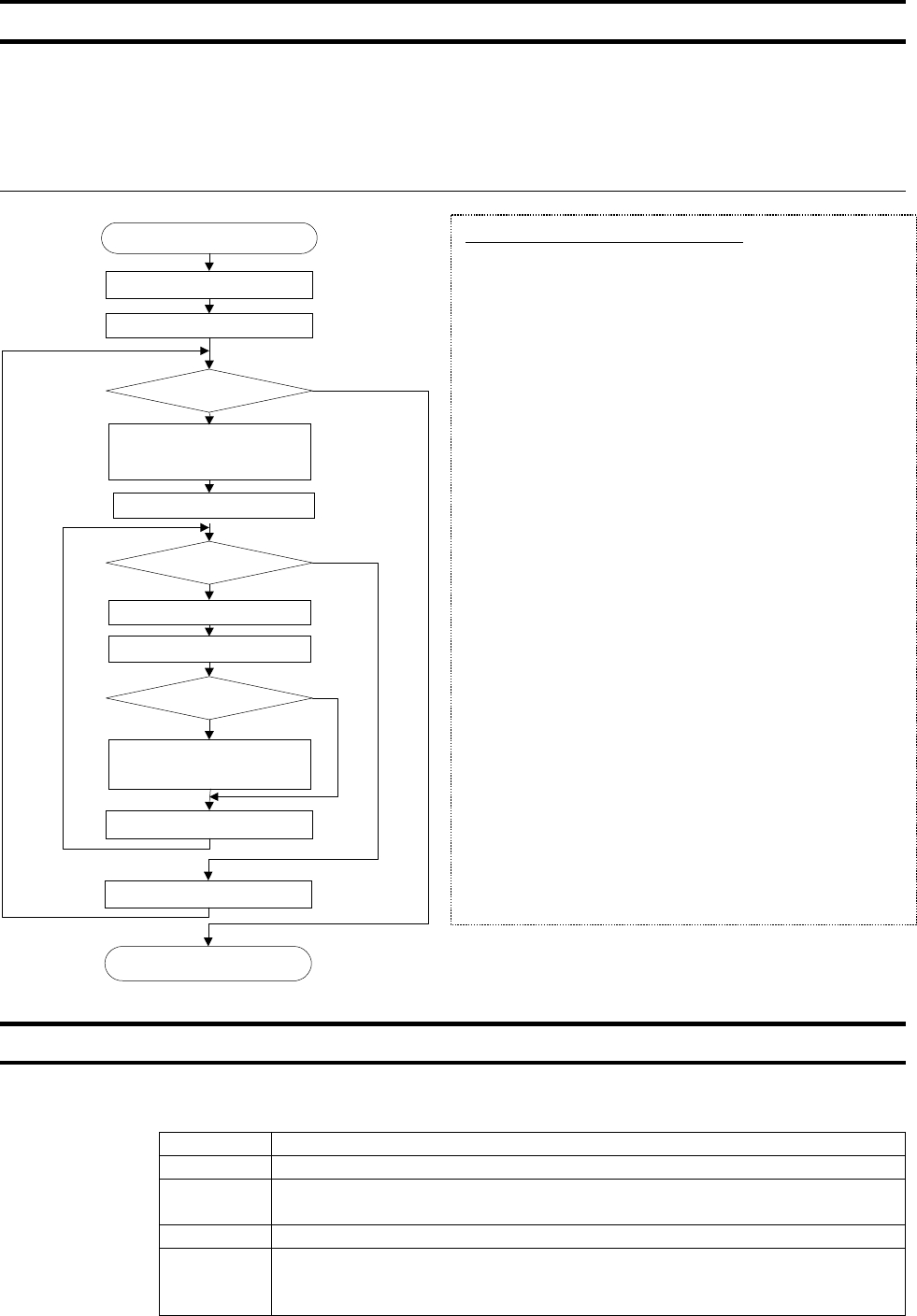
5.2. CRC Generation
“CRC” is a system to check errors in communication frames during data transmission. CRC is
composed of two bytes and has hexadecimal-bit binary values. CRC values are generated by the
transmission side that adds CRC to messages. The receiving side regenerates CRC of received
messages and compares generation results of CRC regeneration with CRC values actually received.
If values do not match, data will be aborted.
Flow
5.3. Error codes
In case of the following errors, the return commands from the inverters are added 80h to the com-
mands received by the inverters. The following error codes are used.
Error Code Description
01 Command error (Returned when a command other than 03 or 06 is received)
02
Communication number error (A communication number is not found when Com-
mand 03 or 06 is received)
03 Data range error (Data range error when Command 03 or 06 is received
04
Unable to execute (Command 06 is being received and data cannot be written)
(1) Writing in write-disable-during-operation parameter
(2) Writing in parameter that is executing TYP
A procedure for generating a CRC is:
1, Load a 16–bit register with FFFF hex (all 1’s). Call this
the CRC register.
2. Exclusive OR the first 8–bit byte of the message with the
low–order byte of the 16–bit CRC register, putting the
result in the CRC register.
3. Shift the CRC register one bit to the right (toward the
LSB), zero–filling the MSB. Extract and examine the
LSB.
4. (If the LSB was 0): Repeat Step 3 (another shift).
(If the LSB was 1): Exclusive OR the CRC register with
the polynomial value A001 hex (1010 0000 0000 0001).
5. Repeat Steps 3 and 4 until 8 shifts have been per-
formed. When this is done, a complete 8–bit byte will
have been processed.
6. Repeat Steps 2 through 5 for the next 8–bit byte of the
message. Continue doing this until all bytes have been
processed.
7. The final contents of the CRC register is the CRC value.
8. When the CRC is placed into the message, its upper
and lower bytes must be swapped as described below.
CRC generation ( )
End (Return CRC)
Byte counter n = 0
Byte counter n < Length
CRC = (CRC XOR n
th
send byte
(0 expanded to word (higher 8
bits))
No
Yes
Bit counter = 0
CRC initial data: FFFF
Bit counter < 8
C = (Remainder of CRC ÷ 2)
Is remainder (C)
other than 0?
(CRC XOR generating polyno-
mial (A001))
Bit counter +1
Byte counter +1
Yes
No
Yes
No
efesotomasyon.com -Toshiba inverter,drive,servo,plc


