


VIVOTEK
User's Manual - 15
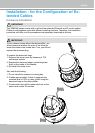
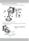
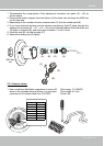
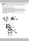
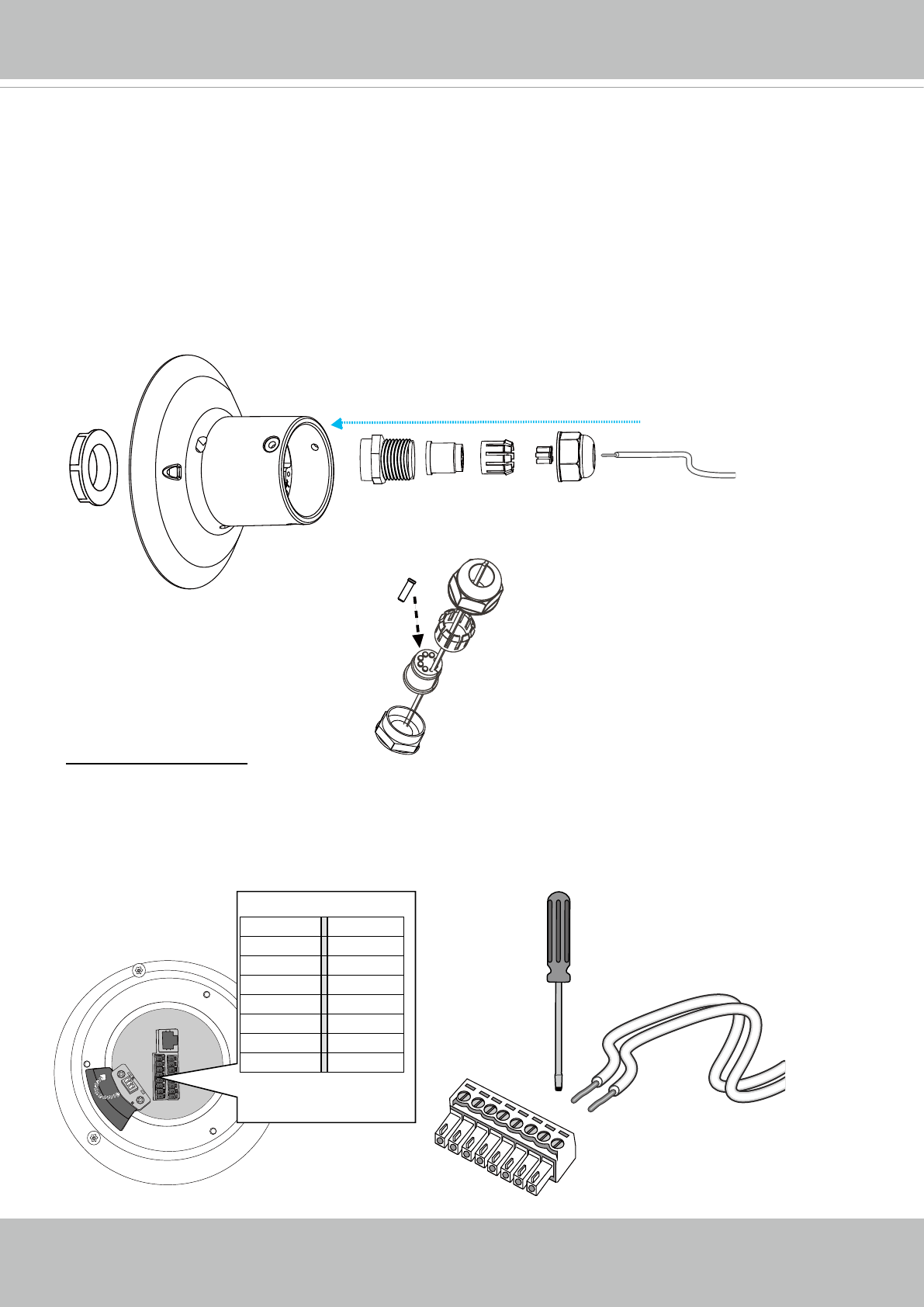
1. Disassemble the components of the waterproof connector into parts (A) ~ (E) as
shown above.
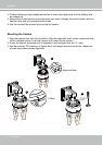
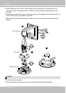
2. Remove the plastic stopper from the bottom of the dome cap and keep the M20 hex
nut for later use.
3. Depending on the number of wires, remove seals (C) from the rubber seal (B).
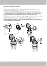
4. If you have external devices such as sensors and alarms, feed IO wires through the
waterproof connector (E --> D --> B --> A) as the illustrated below. Note that there are
16 holes on the seal (B), and wire range is beteen 1.2 and 1.8mm.
5. Push the seal (B) into the housing (D).
6. Secure the sealing nut (E) tightly.
(E)(D)(B)(A)
(C)
(B)
(D)
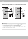
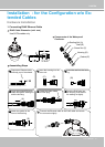
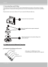
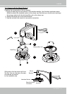
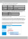
2-2. Connect cables:
Ethernet
DI GND
DI4
DI3
DI2
DI1
DO2
DO1
DO+(12V)
AC24V
AC24V
Reserved
MIC IN
Line OUT
Audio GND
RS485-
RS485+
AC24V DI GND
AC24V DI4
Reserved DI3
MIC IN DI2
Line OUT DI1
Audio GND DO2
RS485- DO1
RS485+ DO+(12V)
Wire range: 13~16AWG
Strip length: 6~7mm
Screw: M2
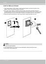
1. Use a small-size at-blade screwdriver to secure IO
wires to the included terminal blocks. You may also
purchase an IO combo cable from VIVOTEK.
M20 hex
nut