


VIVOTEK
8 - User's Manual
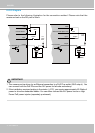
DI/DO Diagram
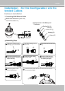
Please refer to the following illustration for the connection method. Please note that the
maximum load on the DO pins is 50mA.
GND
Camera Power
Input
Output
+12
VDC
Max.
VDC
Switch
BJT transistor
GND
Camera Power (DO+ 12V)
Input
Output
+12
VDC
VDC
Switch
BJT transistor
Relay
Relay
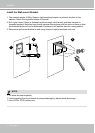
1. The camera can be driven by an Ethernet connection to a PoE Plus switch (30W output). You
can connect both the PoE Plus and the 24V power for fail-safe redundancy.
2. If the installation requires heating in the winter (<-5ºC), you require approximately 60 Watts of
power to drive the embedded heater. You can either connect the 24V power lines or a High
Power PoE power injector (separately purchased).
IMPORTANT: