


975-0390-01-01 7
Features
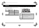
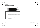
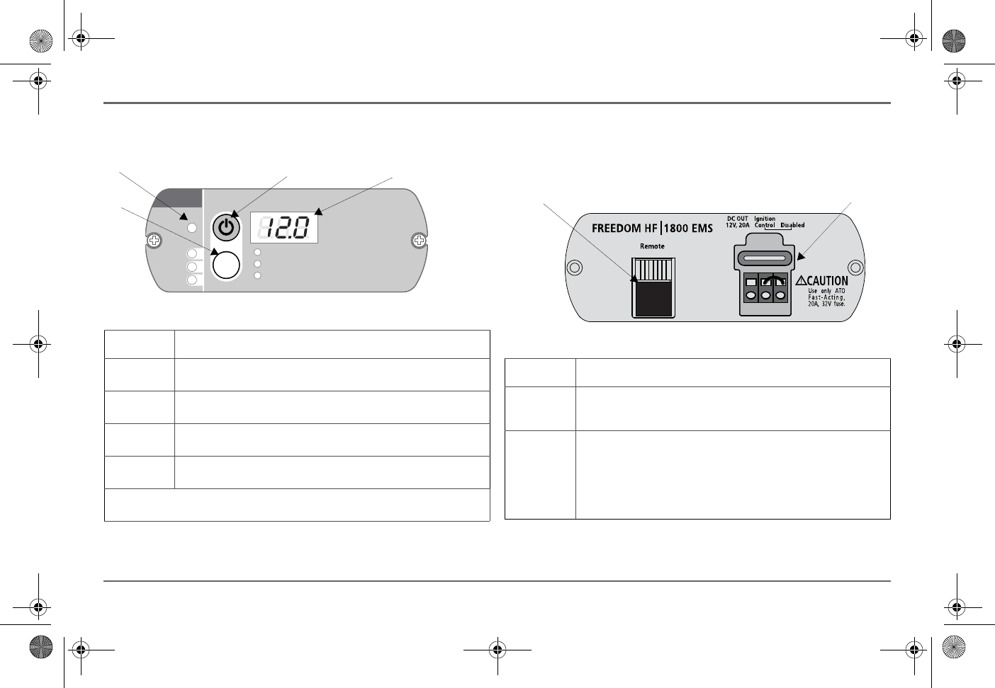
Display Panel (All Models)
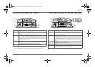
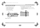
Remote and Power Module Panel
(
Freedom HF 1055 EMS,1800 EMS
)
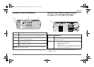
For instructions on how to enable or disable Ignition Control, see the
Installation Guide.
Feature Description
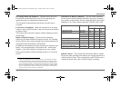
1 Inverter Power button is the main unit switch that turns the Freedom HF’s
inverter function ON or OFF. See page 15 for additional information.
2 Three-digit LED display screen shows status information and fault codes.
See page 15 for additional information.
3 Status LED indicates the mode of operation with a three-color LED. See
page 15 for additional information.
4 Select button changes status information displayed on the display screen. See
page 15 for additional information.
IMPORTANT: See “Display Panel Operation” on page 15 starting on page 15 for detailed
information on operating the panel’s buttons.
FREEDOM HF
Input Voltage(V)
Se lec t
STAT US
Batt er y
Fa ult
Utility
Input Current (A)
Output Power (kW)
4
1
2
3
Feature Description
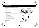
1 Remote jack is used for connecting the Display panel that ships with the
Freedom HF 1055 EMS and 1800 EMS. Each shipment comes with a 25-foot
communications cable as well.
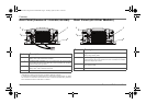
2 Power module has one fuse and three contacts for wires that connect to:
• an auxiliary 12-volt DC OUT terminal,
• an Ignition Control terminal, and
• a Disabled terminal.
NOTE: The Ignition Control and Disabled terminals are connected
by a jumper wire that acts to disable ignition control. Removing the
jumper wire will enable ignition control.
2
1
Freedom HF InvChg Owners Guide.book Page 7 Tuesday, April 29, 2014 12:10 PM