Page 5 of 13 Rev: 1/21/2014 7:17 AM
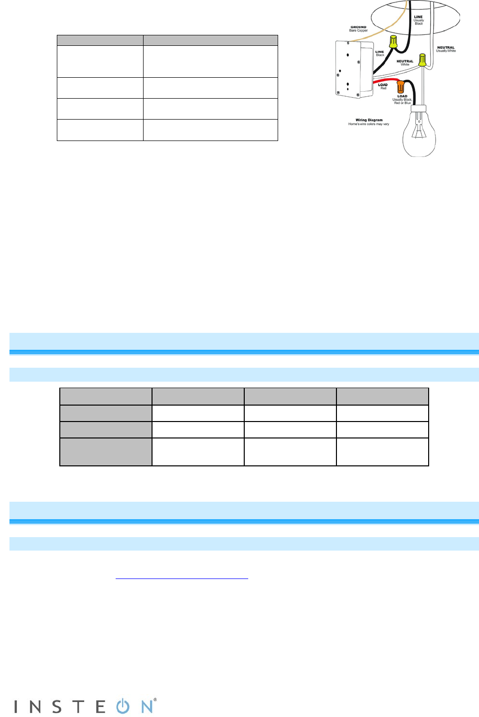
6) Referring to the diagram at right and the table below, use the
included wire nuts to connect the fixture’s Line, Load, Neutral
and Ground wires to In-LineLinc’s corresponding wires.
7) Enable power to the switch from the circuit breaker or fuse
panel.
8) Use In-LineLinc’s On and Off buttons to test that In-LineLinc is installed properly.
The load will turn on and off.
9) Adjust and set the local on-level and ramp rate for the connected load.
10) Link In-LineLinc to an INSTEON controller.
11) Gently place In-LineLinc into the junction box, making sure nothing could accidentally press the
buttons on its face.
12) Reinstall the fixture.
Note: the Neutral wire will not normally be connected to the switch you are replacing. If there is no
Neutral wire in the box, consult an electrician or call the INSTEON Support Line at 1-800-762-7845.
Using In-LineLinc Dimmer
Button Functions
Button Tap Double-Tap Press and Hold
ON
Ramp to on-level Fast on Brighten
Ramp to off Fast off Dim
Set
Set the default
on-level
Sets the default
ramp rate
Starts linking
mode
An Important Note About INSTEON Networks
Split Single-Phase vs. 3-Phase Installation
For the best INSTEON network performance, be sure you have properly installed at least two Access
Points (#2443) or other dual-band INSTEON products
. INSTEON has only been officially tested in a split
single-phase residential environment, but has been known to work in many 3-phase systems with three
dual-band products installed (one on each phase). However, due to the potential complexity of its
troubleshooting, the INSTEON Support Line is unable to support INSTEON in 3-phase environments.
Bare copper
(commonly bare copper, green
White
Neutral
(commonly white wire bundle)
Red
Black
Line
(100 - 277V to Ground)


