22
22
Y
G
Pb
B
Pr
R
V
H
HIGH RESOLUTION INPUT
INPUT
3 PIP
S-VIDEO
VGA
640X 480, 60HZ
COMPONENT 480i /480p
1 (YPrPb)
2 (YPrPb)
DTV (YPrPb/GRBHV)
480i /480p /1080i
VIDEO
MONITOR
IR EMITTER HOME THEATER
21
STB
OUTPUT
AUDIO-
LEFT/
(MONO)
AUDIO-
RIGHT
AUDIO-
LEFT/
(MONO)
AUDIO-
RIGHT
ANT-BLOOP OUTANT-A
TV back panel
A/V Receiver
1
D IG ITA L
SURRO UND
S
CH
Other A/V Device
D IG ITA L
SURRO UND
S
CH
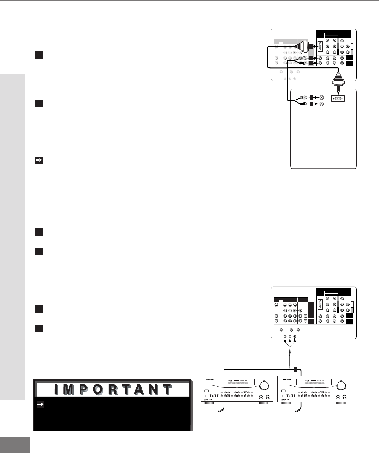
Figure 2. Connecting the System 4 Home Theater IR
Control.
See page 53 for details on using the
TV’s IR emitter to control a Mitsubishi
A/V receiver.
Part II: Installation
Connecting a Computer with a VGA Monitor Output
Connecting a Computer
(Figure 1)
Connect VGA Monitor Out from the com-
puter to VGA on the TV back panel
using a VGA compatible monitor cable.
See Appendix B, page 61, for VGA
signal compatability.
Connect the L (left) and R (right)
audio cables from the computer to VGA
AUDIO on the TV back panel. In cases
where your computer’s audio output is a
single mini-RCA jack, a spliter is needed
to complete this connection.
To utilize the bene ts of a digi tal A/V
receiver, connect your computer’s digital
audio out, if available, to a digital input
on your digital A/V receiver.
Figure 1. Connecting a computer with a VGA monitor
output.
Y
G
Pb
B
Pr
R
V
H
HIGH RESOLUTION INPUT
INPUT
3 PIP
S-VIDEO
VGA
640X480, 60HZ
COMPONENT
480i /480p
1 (YPrPb)
2 (YPrPb)
DTV (YPrPb/GRBHV)
480i /480p /1080i
VIDEO
MONITOR
IR EMITTER HOME THEATER
21
STB
OUTPUT
AUDIO-
LEFT/
(MONO)
AUDIO-
RIGHT
AUDIO-
LEFT/
(MONO)
AUDIO-
RIGHT
ANT-BLOOP OUTANT-A
AUDIO
VGA OUTPUT
L
R
VGA MONITOR
CABLE
VGA MONITOR
CABLE
White
Red
1
2
2
2
2
1
TV back panel
Computer with VGA Monitor Output.
Connect the IR emitter to IR EMITTER
HOME THEATER on the TV back panel.
Place the IR emitter cable under or
along the side of the A/V device. Place
the IR lens directly in front of the A/V
device’s infrared signal receiver. Infra-
red signal receivers are usually behind
the front translucent panel of the device.
Place unused transmitters in an out-of-
the-way location.
For permanent installation of the IR
emitter cable, use the included adhesive
tape to secure the bottom of the emitter
to the anchoring object of your choice.
Connecting the System 4 Home Theater IR Control
(Figure 1)
Connecting a Computer and the System 4 Home Theater IR Control
