


8
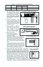
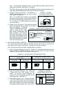
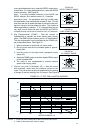
fault). To set the control to automatically reset after a
fault has been cleared, set Jumper J3 to the "AUTO"
position. See Figure 12. (Also see section VIB, on page
9 and Table 4, on page 10.)
WARNING! The motor will automatically
restart when the AC line is applied, if Jumper
J4 is set to the "AUTO" or “MAN” position and the
Start/Stop Switch is eliminated with a jumper
installed between the RUN and COM terminals.
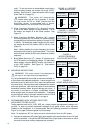
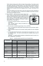
D. Motor Frequency Selection (J5)
– Jumper J5 is facto-
ry set to the “60Hz” position, for 60 Hz motors. For 50
Hz motors, set Jumper J5 to the “50Hz” position. See
Figure 13.
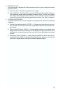
E. Motor Frequency Multiplier Selection (J6) – Jumper
J6 is factory set to the “1X” position, for motor frequency
corresponding to the frequency setting of Jumper J5 (50
or 60 Hz). To double the output frequency to the motor,
set Jumper J6 to the “2X” position (100 or 120 Hz). See
Figure 14.
Note: When doubling the motor frequency, the motor
will produce full torque up to its base speed. The torque
will be linearly reduced to 50% at the maximum doubled
frequency.
F. Boost Mode Selection (J7): Jumper J7 is factory set to
the "FIX" position, for fixed boost voltage. For adjustable
boost voltage, using the BOOST trimpot, set Jumper J7
to the "ADJ" position. See Figure 15. (See section
VIIIG, on page 12).
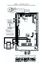
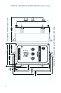
IV. MOUNTING INSTRUCTIONS
WARNING! This motor control is not designed to
be used in an explosion-proof application.
It is recommended that the control be mounted vertically on
a flat surface with adequate ventilation. Leave enough room
below the control to allow for AC line, motor connections and
any other wiring. Although the control is designed for outdoor
and wash down use, care should be taken to avoid extreme
hazardous locations where physical damage can occur. If
the control is mounted in a closed, unventilated location,
allow enough room for proper heat dissipation. If operating
the control at full rating, a minimum enclosure size of 12”W X
24”H X 12”D is required. See Figure 3, on page 4.
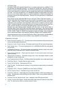
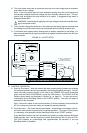
V. RECOMMENDED HIGH VOLTAGE DIELECTRIC
WITHSTAND TESTING (HI-POT)
Testing agencies such as UL, CSA, VDE, etc., usually require that equipment undergo a hi-
pot test. In order to prevent catastrophic damage to the speed control, which has been
installed in the equipment, it is recommended that the following procedure be followed.
Figure 16, on page 9 shows a typical hi-pot test setup.
Note: All equipment AC line inputs must be disconnected from the AC power.
A. Connect all equipment AC power input lines together and connect them to the H.V. lead
of the hi-pot tester. Connect the RETURN lead of the hi-pot tester to the frame on which
the control and other auxiliary equipment are mounted.
!
FIGURE 12 – RESTART
MODE SELECTION
FIGURE 13 – MOTOR
FREQUENCY SELECTION
J5 Set for
60 Hz Motors
(Factory Setting)
J5 Set for
50 Hz Motors
J5
60 Hz
50 Hz
FREQ
J5
60 Hz
50 Hz
FREQ
FIGURE 14
MOTOR FREQUENCY
MULTIPLIER SELECTION
!
FIGURE 15
BOOST MODE SELECTION
J4 Set for Auto
Reset Mode
J4 Set for Manual
Reset Mode
(Factory Setting)
J4
AUTO
MAN
J4
AUTO
MAN
J6 Set for 1X
Motor Frequency
(Factory Setting)
J6 Set for 2x
Motor Frequency
J6
1X
2X
MULT
J6
1X
2X
MULT
J7 Set for
Adjustable Boost
J7 Set for
Fixed Boost
(Factory Setting)
J7
FIX
ADJ
BOOST
J7
FIX
ADJ
BOOST