


12
The CL trimpot is factory set for 160% of Jumper J3 range setting. For a higher current
limit setting, rotate the CL trimpot clockwise. For a lower current limit setting, rotate the
CL trimpot counterclockwise. The current limit also contains I
2
t trip function. The control
will trip according to a predetermined current vs. time function. The trip curve is directly
related to the CL set point and can be changed with the CL trimpot. See Figure 23 on
page 11.
CAUTION! Adjusting the CL above 160% of the motor rating may cause overheating of
the motor. Do not leave the motor in a locked rotor condition for more than a few sec-
onds since motor damage may occur.
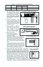
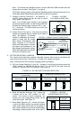
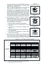
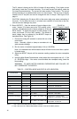
G. Boost (BOOST) – Sets the amount of boost voltage to the
motor. Jumper J7 is factory set to the "FIX" position, which
provides a predefined amount of boost voltage for 50 Hz and
60 Hz motors. To adjust the amount of boost voltage to the
motor, set Jumper J7 to the "ADJ" position. The amount of
boost voltage may be adjusted by the BOOST trimpot as
described below. See Figure 24.
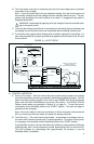
1. Connect an analog AC ammeter in series with one of the
motor leads.
Note: Generally, digital or clamp-on ammeters do not
yield accurate readings.
2. Run the motor unloaded at approximately 4 Hz (or 120 RPM).
Note: An unloaded motor with excessive boost will draw more current than a partial-
ly loaded motor.
3. Adjust the BOOST trimpot until the ammeter reading reaches the motor nameplate
rating.
4. Using the Main Speed Potentiometer, slowly adjust the motor speed over a 0 - 15 Hz
(0 - 450 RPM) range. If the motor current exceeds the nameplate rating, lower the
boost setting.
WARNING! TO AVOID MOTOR WINDING OVERHEATING AND FAILURE, DO
NOT OVERBOOST THE MOTOR.
1 Sec On - 1 Sec Off
1 Sec On - 1 Sec Off
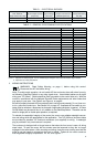
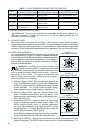
Control Mode
Slow Flash
Status LED Information
Flash Rate Color Sequence Illumination Duration Seconds
Run
Stand-By
1
Short Circuit
I
2
t Fault
Overload
Slow Flash
Slow Flash
Quick Flash
Steady
Undervoltage
Overvoltage
Recovered Undervoltage
2
Recovered Overvoltage
2
1 Sec Red - 1 Sec Yellow - 0.5 Sec Off -
1 Sec Green - 0.5 Sec Off
Quick Flash
Slow Flash
Quick Flash
Slow Flash
Green
Yellow
Red
Red
Red
Red - Yellow
Red - Yellow
Red - Yellow - Off - Green - Off
Red - Yellow - Off - Green - Off
1 Sec On - 1 Sec Off
0.25 Sec On - 0.25 Sec Off
Constant
0.25 Sec Red - 0.25 Sec Yellow
1 Sec Red - 1 Sec Yellow
0.25 Sec Red - 0.25 Sec Yellow -
0.5 Sec Off - 1 Sec Green - 0.5 Sec Off
Notes: 1. Only if the Forward-Stop-Reverse Switch is installed
2. Only if the control is in Manual Reset Mode (Jumper J4 set to the “MAN” position).
TABLE 5 – CONTROL MODE AND STATUS LED INDICATION
9
23
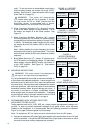
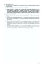
(Shown Factory Set to 5 Volts)
5
16
Volts
0
35
FIGURE 24
BOOST TRIMPOT RANGE
Stop Steady Yellow Constant