


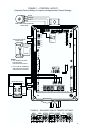
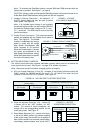
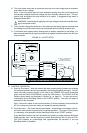
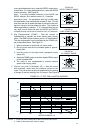

A. AC Line Connection – Wire the
AC line input to L1 and L2 terminals
of Terminal Block TB1 as shown in
Figure 4. Be sure
bothJumpers J1
and J2 are set to the “115V” posi-
tion for 115 Volt AC line input or to
the “230V” position for 208/230 Volt
AC line input.
B. Ground Connection – Earth
ground the control chassis using
the green ground screw that is pro-
vided on the inside of the control to
the right side of Terminal Block TB1
as shown in Figure 4.
C. Motor Connection – Wire the
motor leads to U, V and W termi-
nals of Terminal Block TB1 as
shown in Figure 4. Be sure
Jumper J3 is set to the correspon-
ding motor horsepower rating.
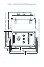
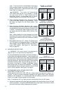
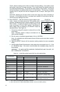
D. Remote Main Speed
Potentiometer Connection –
The control is supplied with a
prewired Main Speed
Potentiometer mounted on the front cover. To
operate the control from a remote potentiometer
(5kΩ), remove the white, orange, and violet
potentiometer leads from P1, P2 and P3 termi-
nals. The leads may be taped and left inside the
control.
The potentiometer assembly may be removed if a
watertight seal is used to cover the hole in the front
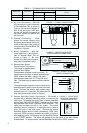
cover. Connect the remote main speed poten-
tiometer wires to P1 (low side), P2 (wiper) and P3
(high side) terminals as shown in Figure 5.
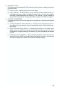
E. Remote Start/Stop Switch Connections – The control is
supplied with a prewired Start/Stop switch, mounted on the
front cover. To operate the control from a remote Start/Stop
Switch (type (ON)-OFF-ON, SPDT), remove the white, black
and red wires from RUN, COM and STOP terminals. The
leads may be taped and left in the control. The switch
assembly may be removed if a watertight seal is used to
cover the hole in the front cover. Connect the remote
Start/Stop Switch wires to RUN (momentary), COM (com-
mon) and STOP (constant) terminals as shown in Figure 6.
After applying power, momentarily set the Start/Stop Switch
to the "START" position. The motor will operate at the set speed of the Main Speed
Potentiometer. To stop the motor, set the Start/Stop Switch to the "STOP" position.
6
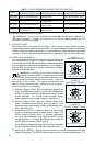
12
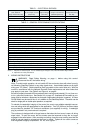
Supply Wire Gauge (AWG - Cu)
Minimum Maximum
Designation Connection
Maximum Tightening Torque
(in-lbs)
AC Line Input
Motor
L1, L2
U, V, W
22 12
22 12 12
TABLE 3 – TERMINAL BLOCK WIRING INFORMATION
TB1
L2
AC LINE
L1
WV
U
MOTOR
AC LINE
MOTOR
(EARTH)
GROUND
FIGURE 4 – POWER CONNECTIONS
P2 P1P3
CON1
(BACK VIEW)
ORANGE (WIPER)
WHITE (LOW)
VIOLET (HIGH)
MAIN SPEED POTENTIOMETER
FIGURE 5 – REMOTE MAIN SPEED
POTENTIOMETER CONNECTION
RED
WHITE
BLACK
START
STOP
START/STOP SWITCH
RUN
COM
STOP
R/F
FIGURE 6 – REMOTE START/STOP
SWITCH CONNECTION
RUN
COM
R/F
STOP
FIGURE 7 – START/STOP
FUNCTION ELIMINATED
(JUMPER INSTALLED)