


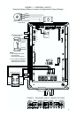
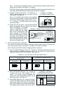

Note: To eliminate the Start/Stop function, connect RUN and COM terminals with the
jumper that is provided. See Figure 7, on page 6.
CAUTION! Using a jumper to eliminate the Start/Stop function will cause the motor to run
at the Main Speed Potentiometer setting when the AC line is applied.
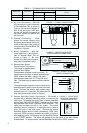
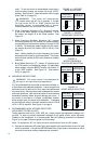
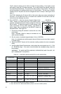
F. Voltage Following Connection – An isolated 0 - 5
Volt DC analog signal can also be used to control
motor speed. See Figure 8.
Note: If an isolated signal voltage is not available,
an optional signal isolator can be installed (ID5SI-2).
Connect the isolated signal voltage to P2 (+) and
P1 (-) terminals. The MIN trimpot must be set fully
counterclockwise.
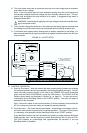
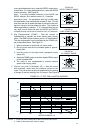
G. Enable Circuit Connection
– The control can also be
started and stopped with an Enable circuit (close to
start). See Figure 9. The Enable
function is established by wiring a
switch in series with the orange
Main Speed Potentiometer lead
which connects to P2 terminal.
When the Enable switch is closed,
the control will accelerate to the
Main Speed Potentiometer setting.
When the Enable switch is opened,
the motor will coast to stop.
III. SETTING SELECTABLE JUMPERS
The control circuit board has customer selectable jumpers which must be set before the
motor control can be used. See Figure 1, on page 3, for location of jumpers.
Note: Disconnect the AC line before changing position of jumpers.
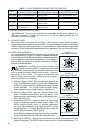
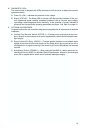
A. AC Line Voltage Selection (J1 and J2) – Jumpers J1 and J2 are bothfactory set to the
“230V” position, for 208/230 Volt AC line input. For 115 Volt AC line input, set
both
Jumpers J1 and J2 to the “115V” position. See Figure 10.
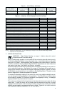
B. Motor Horsepower Selection (J3) – Jumper J3
is factory set to the “1HP” position, for 1HP
motors. For motors of lower horsepower, set
Jumper J3 to the corresponding position for the
motor being used. See Figure 11.
C. Reset Mode Selection (J4) – Jumper J4 is facto-
ry set to the "MAN" position, for manual resetting
of the control every time the AC line is applied or
after a fault condition has occurred (undervoltage,
overvoltage, phase-to-phase short circuit and I
2
t
7
Control Set for 208/230 Volt AC Line Input
(Factory Setting)
Control Set for 115 Volt AC Line Input
J1 Set for 208/230 Volt
AC Line Input
J2 Set for 208/230 Volt
AC Line Input
J1 Set for 115 Volt
AC Line Input
J2 Set for 115 Volt
AC Line Input
J1
230V115V
J2
230V
115V
J1
230V115V
J2
230V
115V
FIGURE 10 – AC LINE INPUT VOLTAGE SELECTION
FIGURE 11 – MOTOR
HORSEPOWER SELECTION
3/4, (0.5)
1/2, (0.37)
J3 Set for 1 HP Motor
(Factory Setting)
Motor Horsepower
HP, (kW)
1, (0.75)
1/4, (0.18)
FIGURE 9 – ENABLE CIRCUIT CONNECTION
SWITCH OR RELAY
(CLOSE TO START)
ENABLE
P2 P1P3
CON1
(BACK VIEW)
VIOLET (HIGH)
WHITE (LOW)
ORANGE (WIPER)
MAIN SPEED POTENTIOMETER
P1P2P3
CON1
+-
0 - 5V DC
(ISOLATED)
FIGURE 8 – VOLTAGE
FOLLOWING CONNECTION