


9
B. The hi-pot tester must have an automatic ramp-up to the test voltage and an automatic
ramp-down to zero voltage.
Note: If the hi-pot tester does not have automatic ramping, then the hi-pot output must
be manually increased to the test voltage and then manually reduced to zero. This pro-
cedure must be followed for each machine to be tested. A suggested hi-pot tester is
Slaughter Model 2550.
WARNING! Instantaneously applying the hi-pot voltage will cause irreversible dam-
age to the speed control.
C. The hi-pot test voltage should be set in accordance to the testing agency standards and
the leakage current should be set as low as possible without causing nuisance trips.
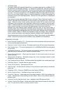
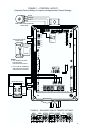
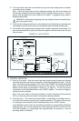
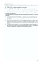
D. To eliminate motor speed control damage due to auxiliary equipment hi-pot failure, it is
also recommended that all signal inputs be wired together and connected to the AC input
lines as shown.
VI. CONTROL OPERATION
A. Start-Up Procedure – After the control has been properly setup (jumpers and trimpots
set to desired positions and wiring completed), the startup procedure can begin. If the AC
power has been properly brought to the control, the POWER LED will be illuminated
green once the Power On/Off Switch is set to the “ON” position. The STATUS LED will
indicate control status as described in Section IX, on page 13. To start the control,
momentarily set the Start/Stop Switch to the "START" position. The motor will begin to
accelerate to the set speed.
Note: If the motor rotates in the incorrect direction, it will be necessary to disconnect the
AC line, reverse any two motor leads, and repeat the startup procedure.
B. Fault Recovery – The control has four fault states – undervoltage, overvoltage, short cir-
cuit at the motor (phase-to-phase) and I
2
t overload protection. To recover from any fault,
it is necessary to momentarily set the Start/Stop Switch to the "START" position.
If the Start/Stop function has been eliminated by installing a jumper between RUN and
COM terminals, then it will be necessary to either disconnect the AC line until the STA-
TUS LED indicates an undervoltage fault (approximately 20 seconds) or use the
Start/Stop Switch (if installed).
21
30
AC KILOVOLTS
RETURN
H. V.
(MAIN POWER DISCONNECTED)
TERMINALS TOGETHER
CONNECT ALL SPEED CONTROL
HIGH VOLTAGE DIELECTRIC WITHSTAND TESTER
MOTOR SPEED CONTROL
(HI-POT TESTER)
SIGNAL INPUTS
TERMINALS
L1
L2
FRAME
CHASSISCHASSIS
MOTOR
MOTOR WIRES
AC LINE INPUTS
RESET
TEST
TO BOTH
CONNECT HI-POT
AC LINE INPUT
LEAKAGE
0mA 10mA
MAX
ZERO
VOLTAGE
AUXILIARY EQUIPMENT
MACHINE OR EQUIPMENT FRAME
L1
L2
P1
P2
P3
FIGURE 16 – HI-POT SETUP
!