


• Low-voltage shutdown (activates at 10.0 volts DC)
• High-input voltage shutdown (activates at above 15.5 volts DC)
MAXX SST™ uses a 12 volt DC power source like those found in motor vehicles, or it can be operated using
multiple battery configurations with commercial battery chargers or solar battery chargers. For most heavy-duty
applications, a multiple battery configuration and the use of deep-cycle batteries is required.
When using multiple batteries, inverters can be operated from one of the vehicle 12 volt batteries, so there’s
always one battery with adequate charge to start an engine.
MAXX SST™ includes a high-surge capability. This is required to start heavy loads, such as motors and other
inductive devices.
WARNING: To reduce the risk of injury or property damage: If the appliance does not work or stops
working, unexpectly, or even momentarily, turn off the appliance and disconnect from inverter until the cause is
identified and corrected.
PRINCIPLE OF OPERATION
The MAXX SST™ inverter converts 12 volt DC (direct current) from a vehicle battery or other 12 volt DC power
source to standard 120 volt AC (alternating current) household power.
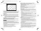
The Power Inverter Output Waveform
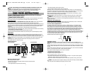
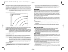
The AC output waveform of the Power Inverter is known as “modified sine wave.” It is a waveform that has
characteristics similar to the sine wave shape of utility power. This type of waveform is suitable for most AC
loads, including linear and switching power supplies used in electronic equipment, transformers, and motors.
The modified sine wave produced by the Power Inverter has an RMS (root mean square) voltage of 120 volts,
which is the same as standard household power. Most AC voltmeters (both digital and analog) are sensitive to the
average value of the waveform rather than the RMS value. They are calibrated for RMS voltage under the
assumption that the waveform measured will be a pure sine wave. These meters will not read the RMS voltage of
a modified sine wave correctly. They will read about 20 to 30 volts low when measuring the output of the inverter.
For accurate measurement of the output voltage of this unit, use a true RMS reading voltmeter such as a Fluke
179, Fluke 79 III series, Beckman 4410 or Triplett 4200.
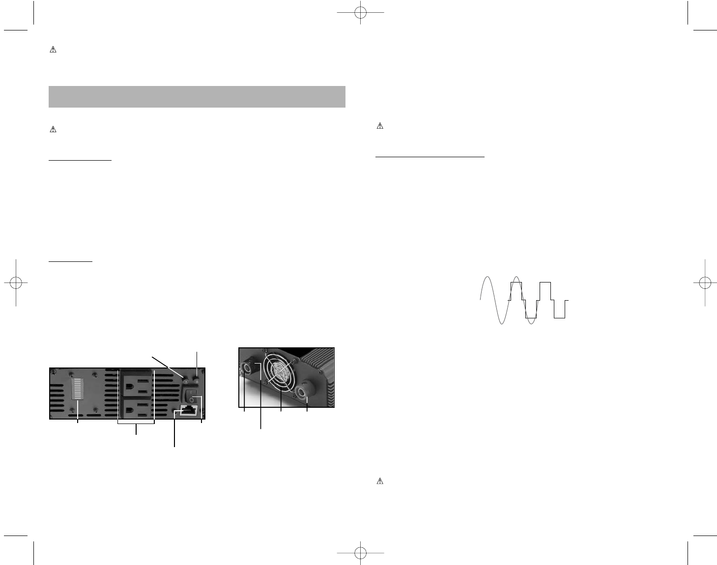
MODIFIED SINE WAVE AND SINE WAVE COMPARISON
Incompatible Products:
CAUTION: Certain products contain power supplies or circuits that are not compatible with an
inverter using a modified sine wave output (such as this inverter) and may be damaged by using this
inverter.
If your product requires pure sine wave AC input power to function properly, the instruction manual
for your product could state this. If in doubt, you should contact your product manufacturer PRIOR
TO USE.
Some products must be powered from a pure sine wave power source, such as standard household
power, or a "pure sine wave" inverter in order to function properly.
Your product could be damaged by this inverter if it contains:
1. Transformer type power supplies
2. Microprocessor controlled power supplies
3. Capacitive coupled power supplies
If an incompatible product is used with this inverter:
•
The product might not operate at all, with no indication of failure. The product fuse might have
opened as a result of trying to use it with the inverter.
•
The product exhibits unusual operation (such as, intermittent operation, buzzing, and the like.)
WARNING:
If the product does not operate normally, to reduce the risk of injury or property damage:
•
Turn the product off immediately and unplug it from the inverter.
SINE WAVE
MODIFIED
SINE WAVE
54
CAUTION: TO AVOID DAMAGE TO THIS INVERTER OR EQUIPMENT YOU INTEND TO USE WITH THIS
INVERTER: For Temporary Installation, only use the Black & Decker/Vector Cable Set identified in the
“Installation” and “Specifications” sections of this Instruction Manual. Permanent Installation must be
performed by a professional as specified in the “Installation” section of this Instruction Manual.
• Read And Understand This Instruction Manual Before Using This Unit.
SAVE THESE INSTRUCTIONS
THIS MANUAL CONTAINS IMPORTANT SAFETY AND OPERATING INSTRUCTIONS FOR THE MAXX SST
TM
COMPACT POWER INVERTER MODEL VEC049DCB.
WARNING: TO REDUCE THE RISK OF INJURY:
Follow these instructions and those published by battery manufacturer and the manufacturer of any equipment
you intend to use with this unit. Review cautionary markings on these products and on engine.
INTRODUCTION
Thank you for purchasing the
VEC049DCB MAXX SST
TM
Compact Power Inverter.
Please read this Instruction
Manual carefully before use to ensure optimum performance and to avoid damage to this product.
This Power Inverter is configured with the latest Soft Start Technology (SST) and supplies continuous power and
peak watts in the form of 120 volt AC outlets to run most household or electronic appliances. Before introduction
of SST, high start-up currents from large inductive loads could shut down an inverter. SST improves inverter
operation by:
•Gradual voltage ramp-up during inverter start-up, eliminating failed cold starts under load.
•Output that momentarily dips in voltage and quickly recovers to allow large motorized loads to start, eliminating
most shutdowns from momentary overloads.
•Soft Start technology dramatically increases reliability and life of the product.
Added safety features include automatic shutdown and a low battery alarm to prevent damage to your battery.
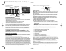
FEATURES
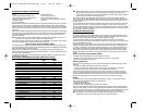
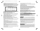
On the front panel are two LED indicators. The green LED indicates power and proper operation of the inverter;
the red LED indicates inverter shutdown from over-load or over-temperature condition, or abnormal input
voltages. The ON/OFF Switch turns the inverter ON and OFF. The switch can also be used to force reset of inverter
circuits by switching it OFF, then back ON again. This unit also features a port to attach a remote control (sold
separately).
120 volt AC power is supplied through two North American three-prong type outlets. The outlets can
accommodate either two- or three-pin AC plugs.
Controls and Functions
Maxx SST™ Automatic Features
Built-in Automatic Features include:
•Overload and over-temperature shutdown activated if AC output exceeds rated watts
•AC short-circuit shutdown
• Low voltage audible alarm (sounds at 10.5 volts input)
PORT FOR
REMOTE CONTROL
(SOLD SEPARATELY)
GREEN POWER LED
INDICATOR
FRONT VIEW DIAGRAM BACK VIEW DIAGRAM
WATTAGE POWER
METER
ON/OFF
POWER
SWITCH
(2) 120 VOLT AC
OUTLETS
RED FAULT
LED INDICATOR
HIGH-SPEED
COOLING FAN
NEGATIVE (–)
TERMINAL
GROUNDING
TERMINAL
POSITIVE (+)
TERMINAL
90550750 VEC049DCB GOOD ONE.qxp 6/5/09 1:46 PM Page 4