


10
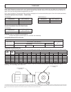
1.6 Mounting Of Reducer with Finished Bore Shaft
1.6.1 Check the internal bore of the reducer and make sure the
snap ring and washer are in the end of the shaft bore opposite
the entry side of the driven shaft.
1.6.2 Check the driven shaft to make sure it is free from
burrs and any rust preventative coating. Lubricate the driven
shaft to ease mounting with reducer. (Anti-Fretting grease is
recommended only for nished bore designs). A lifting lug is only
for lifting the weight of the reducer/gearmotor.
WARNING! (Do not use the lifting lug on the gear housing to
lift additional attached assemblies to avoid overloading the
lifting lug). Never lift gear unit by its output shaft.
1.6.3 Check the driven shaft to ensure the end is tapped. Install
the shaft key in the keyseat.
1.6.4 Rotate the OtN input until the hollow output shaft is aligned
with the key in the driven shaft.
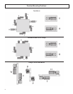
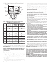
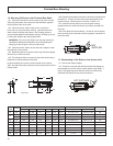
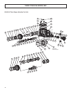
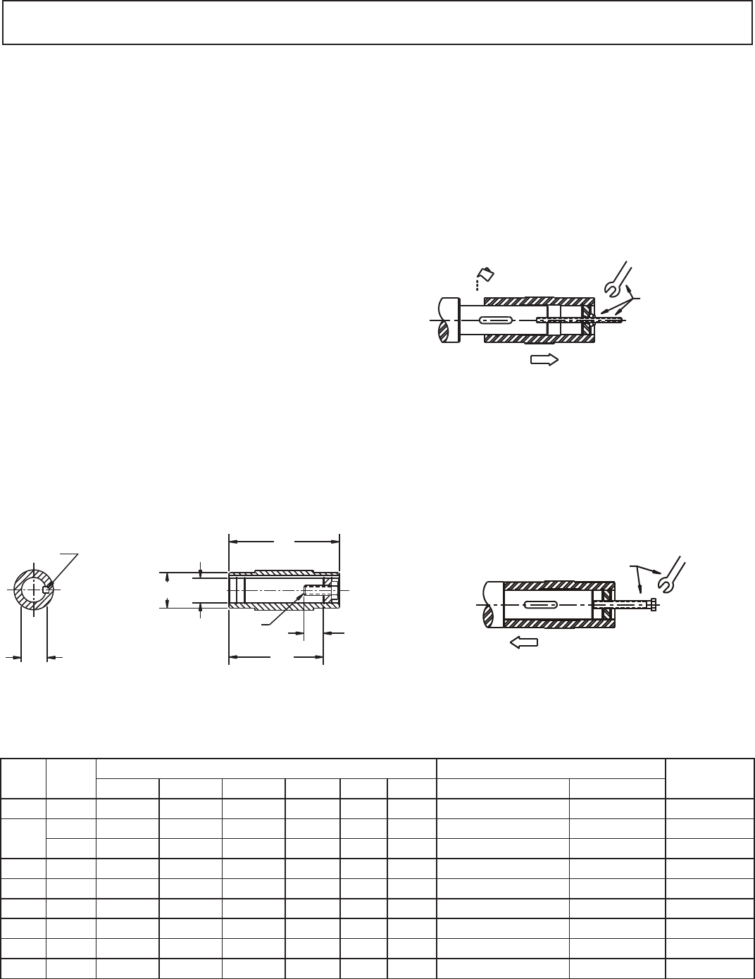
1.6.5 The OtN gear shaft is mounted on the driven shaft using a
threaded rod, and screwed into the shaft.
By then threading a nut down onto the washer in the reducer
shaft, the shaft is smoothly inserted into the cylindrical bore of the
reducer shaft.
NOT SUPPLIED
REMOVAL
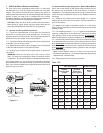
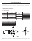
VG
EH
UY
UF U
M
Key
Output Shaft
MH
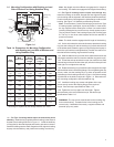
1.6.6 Replace the threaded rod with the bolt that is supplied with
the OtN unit. Thread it into the driven shaft and tighten to the
required torque. See bolt torque as shown in Table 1.2.5.
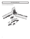
1.6.7 Install the hollow shaft cover onto the gear housing
opposite the driven shaft with the two (2) screws provided with
the cover.
1.6.8 Drive Shaft Recommendations - Its best to use the keeper
bolt to pull the driven shaft into the quill up against a shoulder on
the driven shaft.
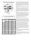
1.7 Dismounting of the Reducer from driven shaft
1.7.1 Secure the reducer weight.
1.7.2 Thread in a long bolt that has the same thread design as
the threaded core of the reducer shaft’s washer (see Table 7-1
below). By tightening down that bolt, the driven shaft will be
separated smoothly from the reducer shaft bore.
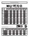
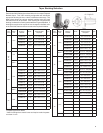
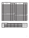
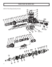
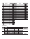
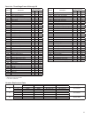
Finished Bore Mounting
Gear
Frame
Version
Reducer Shaft Driven Shaft
Keeper Washer
Thread UNC
EH U UF UY VG MH Key
1
M (inches)
31 S2 5.12 1.250 1.77 1.372 4.31 0.37 1/4 x 1/4 x 1-1/2 7/16-14 x 1.00 5/8
32
S2 5.94 1.375 1.96 1.523 5.06 0.37 5/16 x 5/16 x 1-13/16 1/2-13 x 1.00 5/8
S3 5.94 1.250 1.96 1.372 5.19 0.37 1/4 x 1/4 x 1-13/16 7/16-14 x 1.00 5/8
33 S2 6.94 1.500 2.16 1.674 5.96 0.49 3/8 x 3/8 x 2-1/4 5/8-11 x 1.75 3/4
34 S2 8.97 2.000 2.56 2.210 7.44 0.72 1/2 x 7/16 x 2-5/8 5/8-11 x 1.75 3/4
35 S2 9.66 2.375 3.54 2.638 8.15 0.85 5/8 x 5/8 x 3-3/8 3/4-10 x 2.0 7/8
36 S2 12.44 2.750 3.93 3.037 10.89 1.23 5/8 x 5/8 x 5-1/2 3/4-10 x 2.0 1
37 S2 13.59 3.625 4.72 4.019 11.9 1.23 7/8 x 7/8 x 5-1/2 3/4-10 x 2.0 1
38 S2 13.74 4.00 5.50 4.316 11.69 1.58 1 x 1 x 6 1-8 x 2.5 1.25
1
the key for the frame 34 is supplied by Browning
MOUNTING
NOT
SUPPLIED