


5
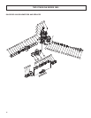
1. OtN Shaft Mount Reducer Installation
For long service and dependable performance, an OtN shaft
mounted gear unit must be properly supported and accurately
aligned. The following instructions are a step-by-step guide to
meeting these requirements for an OtN 3000 design shaft mounted
product. If there is a need to vary or deviate from any of these
installation instructions, contact Application Engineering Department
at 1-800-626-2093 before completing the installation.
CAUTION: When the driven shaft is smaller than the maximum
bushing size for a gear frame, check the driven shaft and key
stress per ANSI/AGMA Std. 6001-D97 for the application.
1.1 Reducer and Driven Shaft Preparation
1.1.1 The driven shaft diameter is to be within the commercial
tolerances for turned, ground and polished bars. The key and
keyseat in the driven shaft are to be in accordance with commercial
standards for the size, depth, offset, and parallelism.
1.1.2 The driven shaft on which the gear unit is to be mounted must
be straight, clean, and free of burrs.
1.1.3 Rotate the driven shaft on which the gear unit is to be mounted
so that the shaft keyseat is in the upward position.
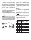
1.1.4 A lifting lug is provided to lift the gear reducer or gearmotor
into position.
WARNING! Never lift the gear unit by the input or output
shaft. The lifting lug is designed for lifting only the gear reducer
or gearmotor. Do not use the lifting lug to lift attached assemblies.
Do not apply grease, oil, or any anti-seize compounds to the taper
bore of the reducer, barrel of the bushing, driven shaft or the bushing
bore. If any of these substances are applied, equipment failure and
personal injury may result.
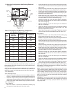
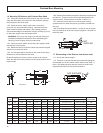
1.2 Determine Mounting Conguration – Bushed Bore Models
Due to the unique design of OtN bushed shaft mounted product,
the reducer may be mounted to the driven shaft in a variety of
congurations. The following instructions will help to determine the
correct mounting conguration based on the available shaft and
key length
1.2.1 Measure the available driven shaft length “H” (in inches)
starting with the end of the driven shaft to the rst obstruction or
point of interference.
1.2.2 Measure the length of available keyseat “K” in the driven
shaft (in inches) starting from the end of the shaft to the end of the
useable keyseat.
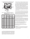
1.2.3 The following sections 1.3, 1.4, 1.5 show the three standard
mounting congurations for the Browning
®
OtN tapered bushed
“33B” gearing. Refer to the following sections in sequence to
determine the optimum mounting conguration for your application.
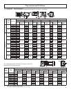
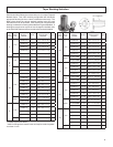
1.2.4 Compare the measured values of H and K of the driven shaft
to the tabulated values of H and K. If the measured values for H and
K are greater than the tabulated values, the mounting conguration
shown in the gure may be used. If the measured values for H and
K are less than the tabulated values, proceed to the next gure
and repeat this step.
Note: If the measured values for H and K are less than the
tabulated values shown in 1-5, contact the Application Engineering
Department at 1-800-626-2093.
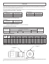
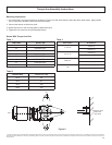
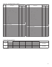
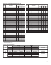
1.2.5 Tightening torque for bushing components.
Gear
Frame
33B Taper Bushed Screw Conveyor
Tapered
Bushing Cap
screws
End Cap
Setscrews
(nylon tipped)
Keeper
Bolts
Size Ft.-Lbs Size In-Lbs Size Ft.-Lbs
31 5/16-18 16 1/4-20 60 - -
32 5/16-18 16 1/4-20 60 1/2-13 99
33
1
5/16-18 16 1/4-20 60 1/2-13 99
33A 3/8-16 29 1/4-20 60 - -
34 3/8-16 29 1/4-20 60 5/8-11 200
35 3/8-16 29 1/4-20 60 3/4-10 350
36 3/8-16 29 1/4-20 60 3/4-10 350
37 1/2-13 70 1/4-20 60 1-8 600
38 1/2-13 70 1/4-20 60 1-8 600
1
This design is replaced by 33A design effective Jan. 2010 for 33B output
Table 1.2.5
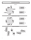
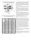
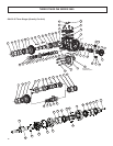
TYPE 2
BUSHING
KEY SHOWN
FOR TYPE 2
BUSHING
BUSHING
RING
BUSHING
Figure 1-1
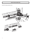
Figure 1-2
THROUGH KEY FURNISHED
TYPE 2
BUSHING
BUSHING
FLANGE
TYPE 1
BUSHING
EXTERNAL KEY
EXTERNAL KEY FURNISHED