


7
Note: Key length must be sufcient to engage the full length of
the bushing. The shaft must engage the full length of the bushing.
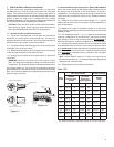
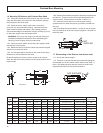
1.4.2 For Type 2 bushings which require one through key:
Install the bushing on the shaft, anged end rst. Align the keyway
in the bushing with the keyseat in the shaft and install the shaft key.
Position the shaft key ush against the inside ange surface of the
bushing. See Figure 1-2 Shaft Key and Bushing Location.
Note: There are three (3) series of bushing keys used in the Type
2 bushing system: rectangular, square and offset. In most cases,
the key supplied will be rectangular or offset. Use caution when
installing rectangular keys as some may visually appear square.
The key should install in the bushing keyway with a sliding type
t. The key in the driven shaft keyseat should be retained to
prevent movement.
Note: The shaft must be engaged the full length of the bushing.
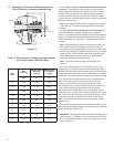
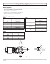
1.4.3 On the side where the driven shaft enters, thread the bushing
ring onto the hollow quill until the bushing ring is ush with the end
of the hollow shaft. Rotate the gear unit input to align the keyway in
the hollow quill with the bushing/shaft key. Position the reducer on
the shaft with the bushing ring toward the bushing.
1.4.4 Slide the stabilizer ring onto the driven shaft with the small end
of the taper toward the reducer. Insert the stabilizer ring into the quill.
1.4.5 Thread the end cap and the dirt cover (not used if driven shaft
extends beyond the end of the hollow quill) onto the hollow quill until
hand tight. Do not tighten the end cap.
1.4.6 Rotate the bushing ring clockwise until the tapped holes align
with the drilled holes in the bushing ange. Prior to tightening the cap
screws, make sure the bushing key is as close as possible to the
inside ange of the bushing as shown in Figure 1-2 and the bushing
is positioned on the shaft as required in Figure 1-4. Dimensions for
rear mounting conguration with the stabilizer ring.
1.4.7 Install the bushing cap screws and tighten all the cap
screws evenly around the bushing ange to the required
torque. See bolt torque specications Table 1.2.5.
1.4.8 Tighten the end cap again until hand tight. Tighten
the setscrews to the recommended torque. See bolt torque
specications Table 1.2.5.
WARNING! The cap screws must thread into the bushing ring
and not the bushing. Threaded holes in the bushing are for
removal only. If assembled incorrectly, equipment failure and
personal injury may result.
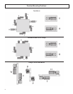
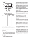
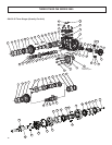
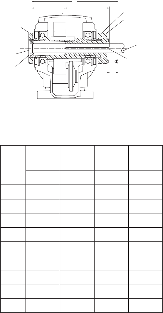
Driven
Shaft Keyseat
Dirt
Cover
Stabilizer
Ring
Driven
Shaft
MC
H
K
J
Endcap
Bushing
Bushing Ring
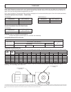
1.4 Mounting Conguration with Bushing on Load
Side of Reducer and Using Stabilizer Ring
Figure 1-4
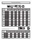
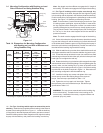
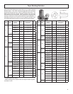
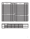
Table 1-4 Dimensions for Mounting Conguration
with Bushing on Load Side of Reducer and
Using Stabilizer Ring
Gear
Frame
Bolt
Clearance
Minimum
Shaft
Mounting
Length
Minimum
Key
Connection
Length
Max.
MC H K J
31 1.50 9.11 2.88 4.73
32 1.75 10.54 4.38 4.28
33
1
1.75 10.47 4.38 4.21
33A 1.88 12.23 4.63 5.83
34 1.88 12.51 4.63 6.01
35 1.88 13.13 5.63 5.62
36 1.88 17.50 6.13 9.49
37 2.25 19.76 7.38 10.13
38 2.75 19.05 7.38 7.74
1
This design is replaced by 33A design effective Jan. 2010
1.4.1 For Type 1 bushings which require an external key and a
shaft key: Install the key (supplied with the bushing) in the external
keyseat of the bushing as shown in Figure 1-1. Install the shaft key
(not supplied) in the shaft keyseat and retain to prevent movement.
Install the bushing onto the shaft, anged end rst, align the bushing
keyway with the shaft key and position the bushing over the key.