


3
Instruction Manual 402 and 402VP
LIQ_MAN_ABR_402_402VP January 2014
1. Make sure the system is shut down and there is no residual pressure.
2. Attach the ball valve (2) to the process piping using the 1–¼-inch FNPT port on the valve or the 1–¼ inch NPT nipple
(1). Use pipe tape on male threads.
3. Slide the handle lock up on the ball valve handle and close the ball valve (2). If the process will be restarted before the
sensor is installed, make sure the system pressure is at or below 542 kPa abs (64 psig) before proceeding. If the system
will not be restarted until after the sensor installation, leave the valve in the open position.
4. If the sensor includes a junction box (8), it must be removed from the sensor to install the retraction assembly kit.
Disconnect the sensor wires inside the junction box prior to disassembly.
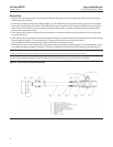
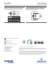
5. Follow Figure 4 to assemble the sensor and retraction assembly. Keep items 3-7 in the proper sequence. Items 3, 6, and
7 are factory assembled.
6. Position the sensor tube (9) so that the electrodes (11) are completely withdrawn inside the packing adapter (3). If it is
difcult to slide the sensor through the packing rings, loosen the packing bushing (6).
7. Position the clamp (4) on the sensor tube (9) so that the electrodes (11) will be completely immersed in the process
liquid when the sensor is fully inserted through the ball valve. See Figure 3. Use the hex key to secure the clamp to the
sensor tube.
8. Slide the retainer (5) onto the sensor tube (9).
9. Screw the junction box (8) — hand tight — onto the sensor tube (9). DO NOT OVERTIGHTEN. Use 2-3 wraps of pipe tape
on the tube threads if a NEMA 4 seal is required at the junction box.
10. Apply pipe tape to the packing adapter (3) threads and screw the packing adapter onto the ball valve.
11. Check to ensure that the packing bushing (6) has been tightened. You should be able to push the sensor tube (9)
against the resistance provided by the packing rings (7).
12. Open the ball valve (2).
13. There may be some leakage around the packing bushing (6). Tighten the packing bushing to stop the leak. Use the
junction box (8) or sensor rear to push the sensor through the valve until the clamp (4) rests against the packing
bushing.
14. To secure the sensor tube (9) in place, tighten — hand tighten only — the retainer (5) against the back of the packing
adapter (3). If the sensor tube retracts when the system pressure is increased, reduce the pressure to 542 kPa abs (64
psig) or less, remove the retainer (5), and tighten the screw in the clamp (4).
Figure 4. 402 Sensor Installation